So, we got the kid a Talaria Sting for his 15:th birthday and soon thereafter he flipped it while trying to wheelie. It’s bound to happen and with the original tail ”extension” on the Talaria the entire rear is scrap after such an incident. Tail light, indicators, subframe.. everything is scratched, crushed or bent.
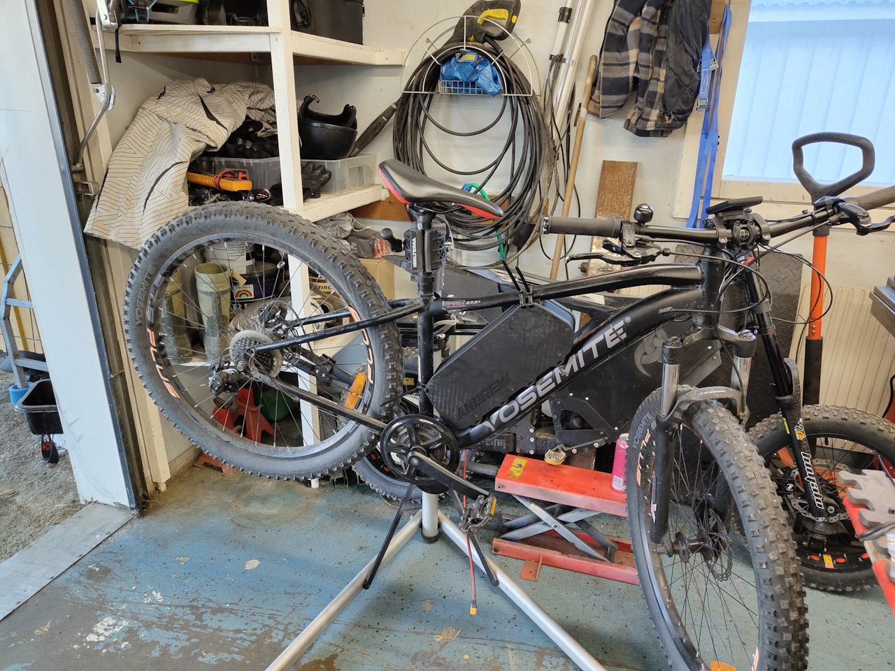
I didn’t get to take any pictures of the bike in that state but after removing the damaged parts and making a quick fix, this is what it looked like.
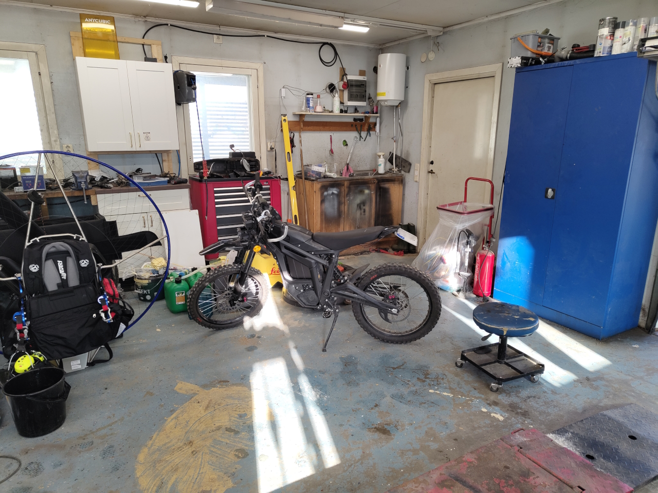
It’s mostly alright and usable but unfortunately the plate hits the rear wheel when compressing the suspension all the way, and that won’t work. So I started working on an upgrade.
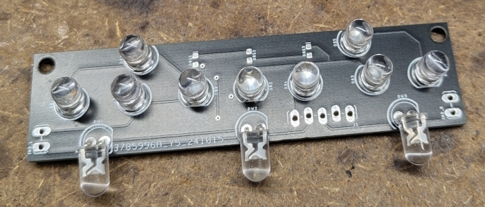
Since the tail light got shattered I started designing a new light that would integrate to the rear part:
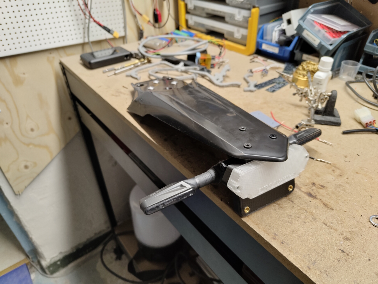
I then designed a plate holder with the integrated tail light and holders for the indicators. I made the indicator holders from TPU so they’d rather bend than cause the indicators to break when hitting stuff..
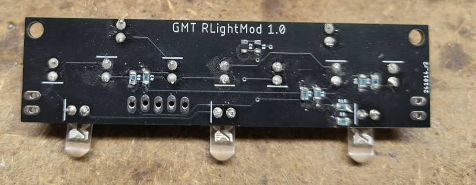
The light casing is made from transparent PLA, even though it looks more white. The light shines through OK but I’ll try tweaking the settings to getting a more transparent print. The lower threads are for bolting the plate to and the light has three integrated white LED:s to illuminate the plate.
Everything is connected using JST-connectors so next crash it’s going to be a quick job replacing whatever’s broken
I’ll post an update when this is mounted on the bike. I might have to adjust the angle of the plate to get it perfect but with this being the longer fender we’ve got a lot more clearance than with the original short one.
The summer has all but gone, and I’m still not nearly done with the electric conversion. The house on the other hand is a lot closer to finished and when that’s done there’ll be much more time for hobby projects like this. 🙂
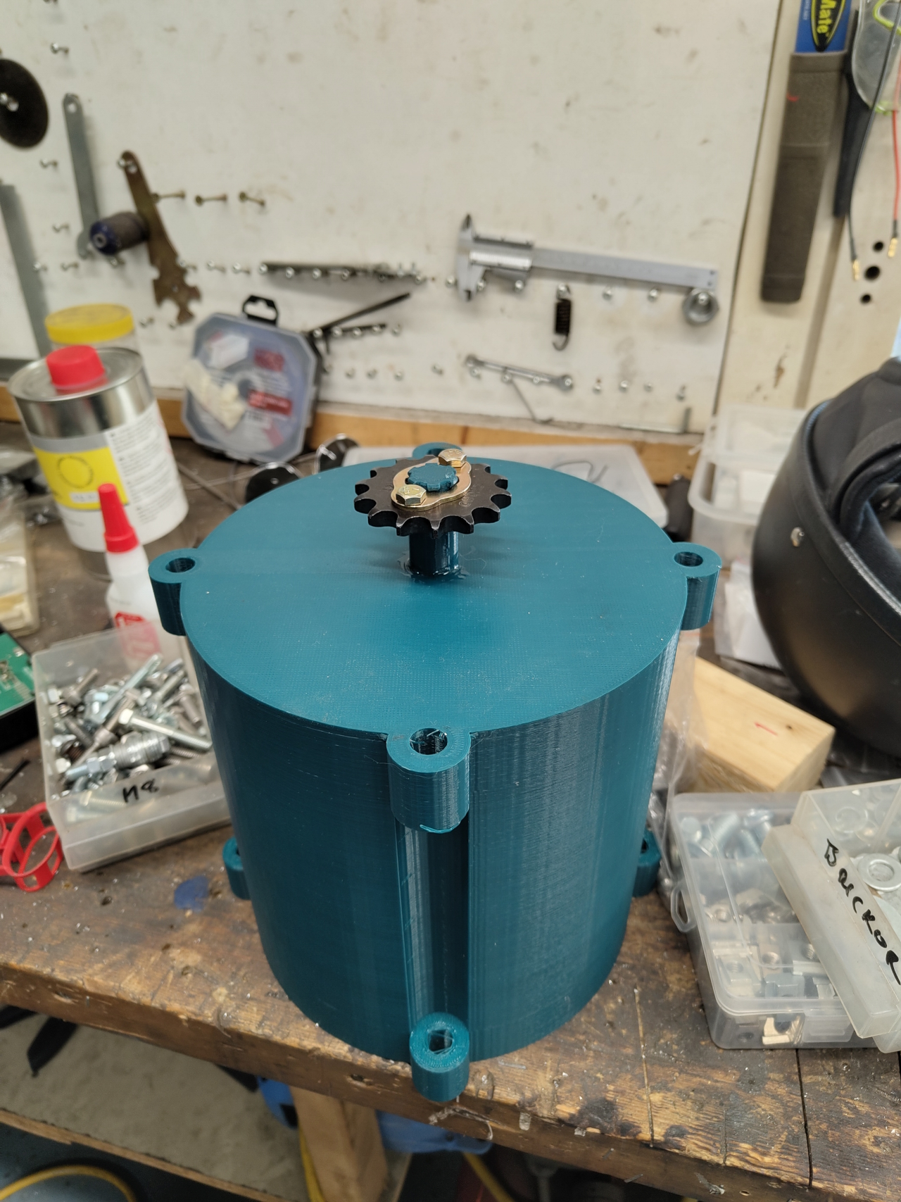
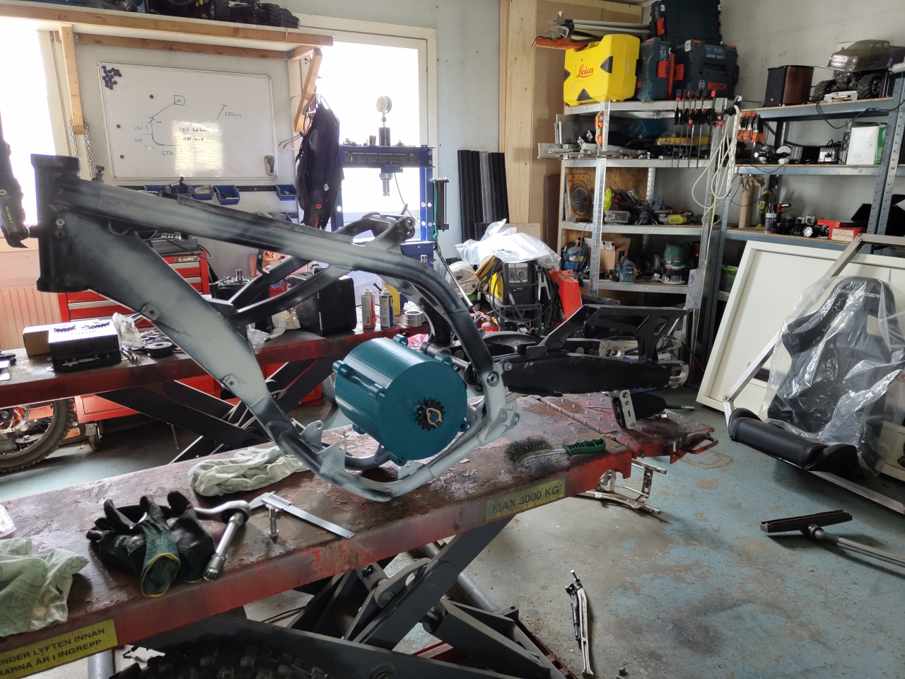
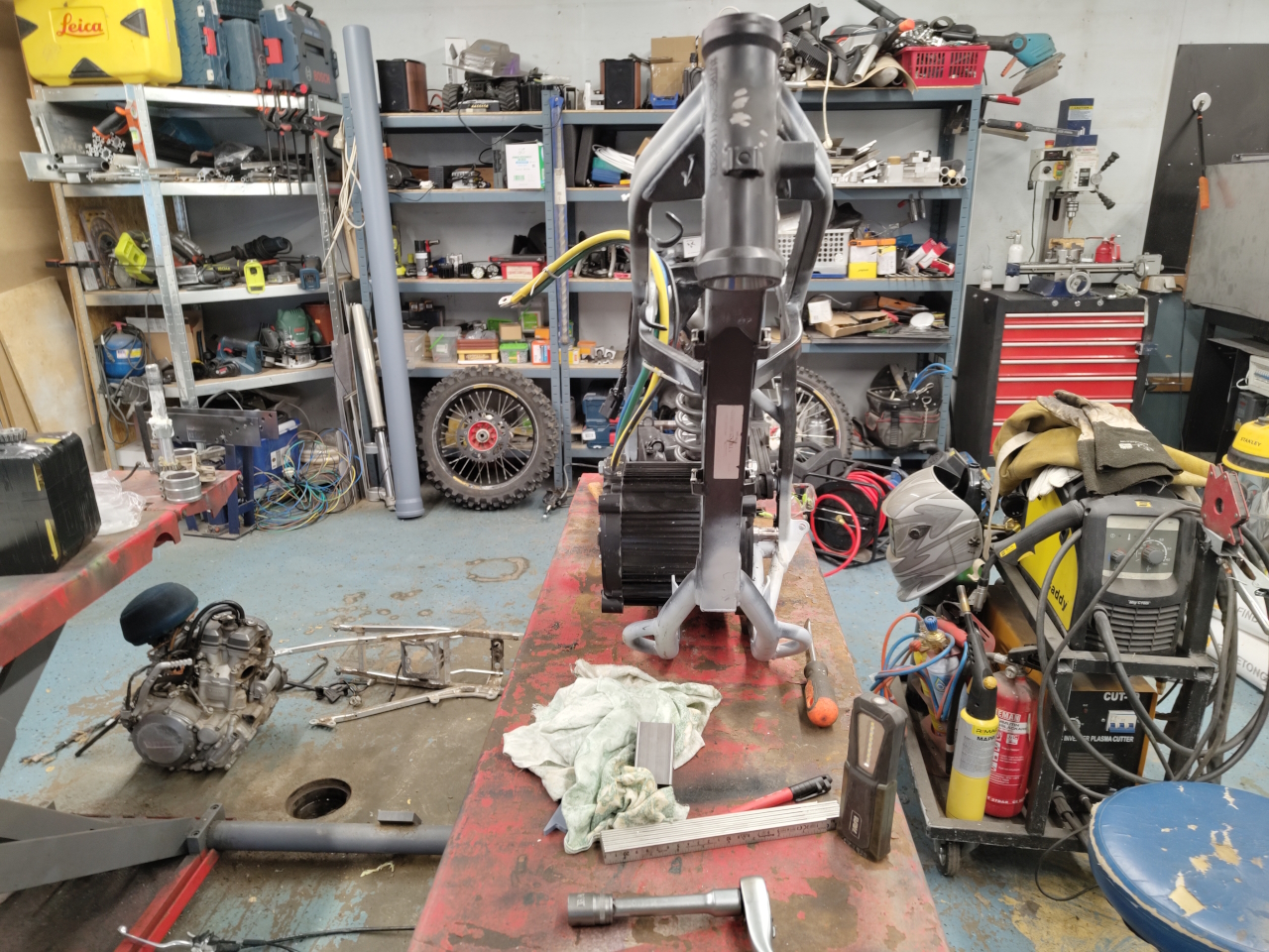
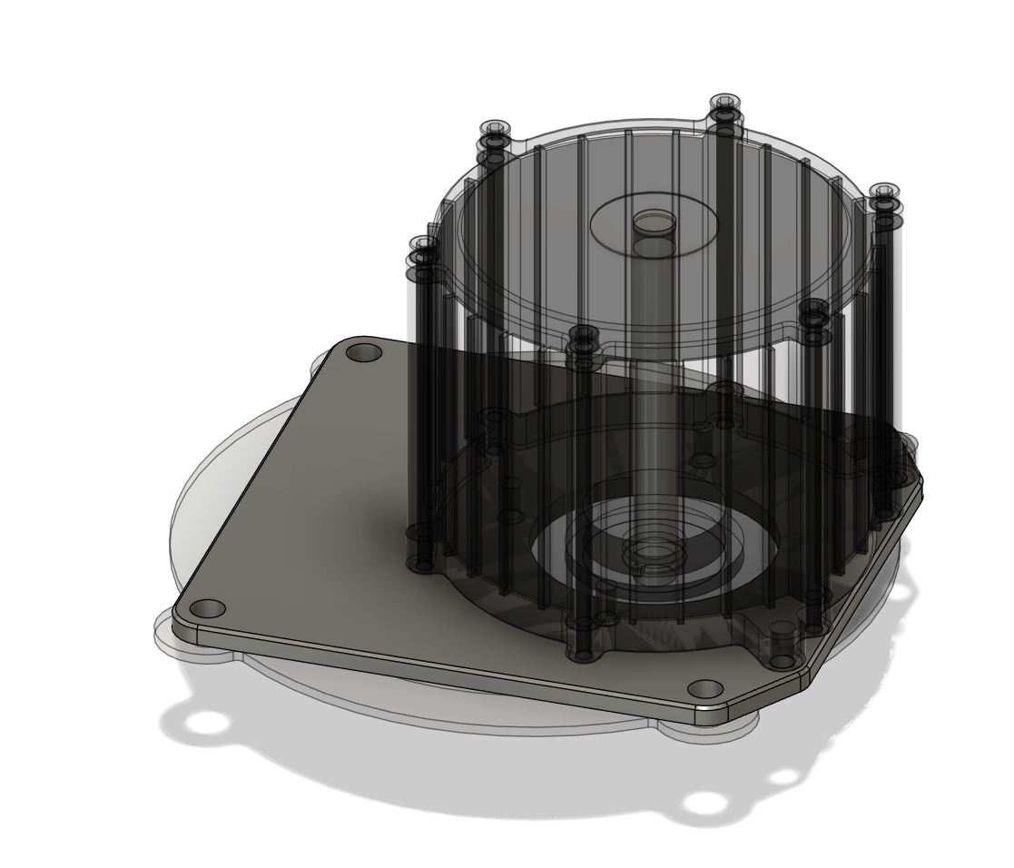
The QS180 motor is a heavy beast and to be able to mock the location for the motor in the frame I 3D-printed a shell with the same dimesions as the motor.
This makes moving the mount around to find the perfect alignment much easier than using the proper motor.
Before starting the building of the bike I had to do some maintenance to the frame though.
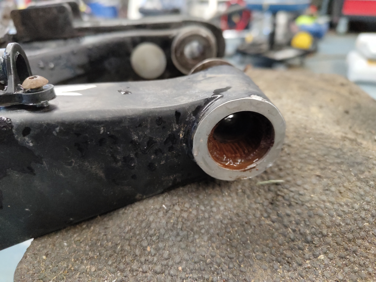
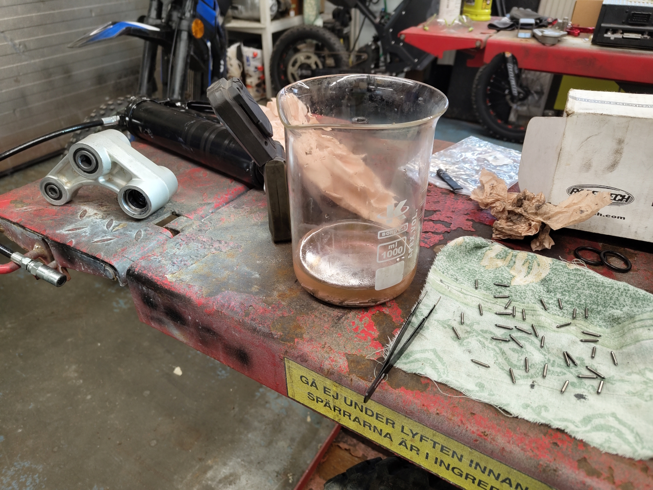
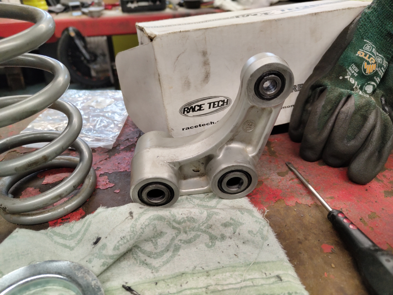
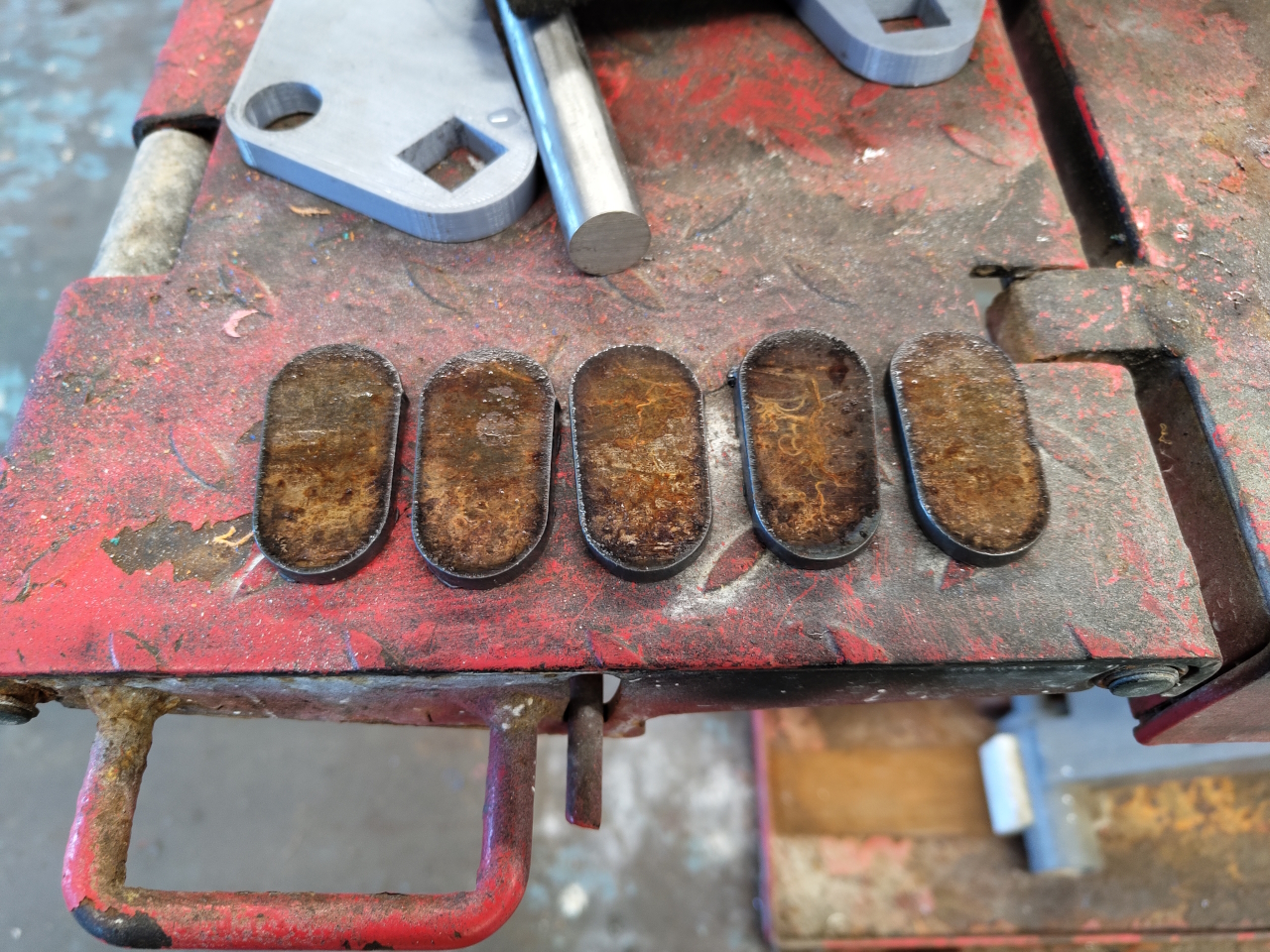
The swingarm bearings were long past their due date and consisted more of a rusty goo than actual rollers. The bushings did not rotate in the bearings, so these had to be replaced. The bearings in the dogbone were in better shape and after a good rinse and lube were working alright.
After replacing and restoring the bearings I could mount the swingarm on the frame to check for motor alignment..
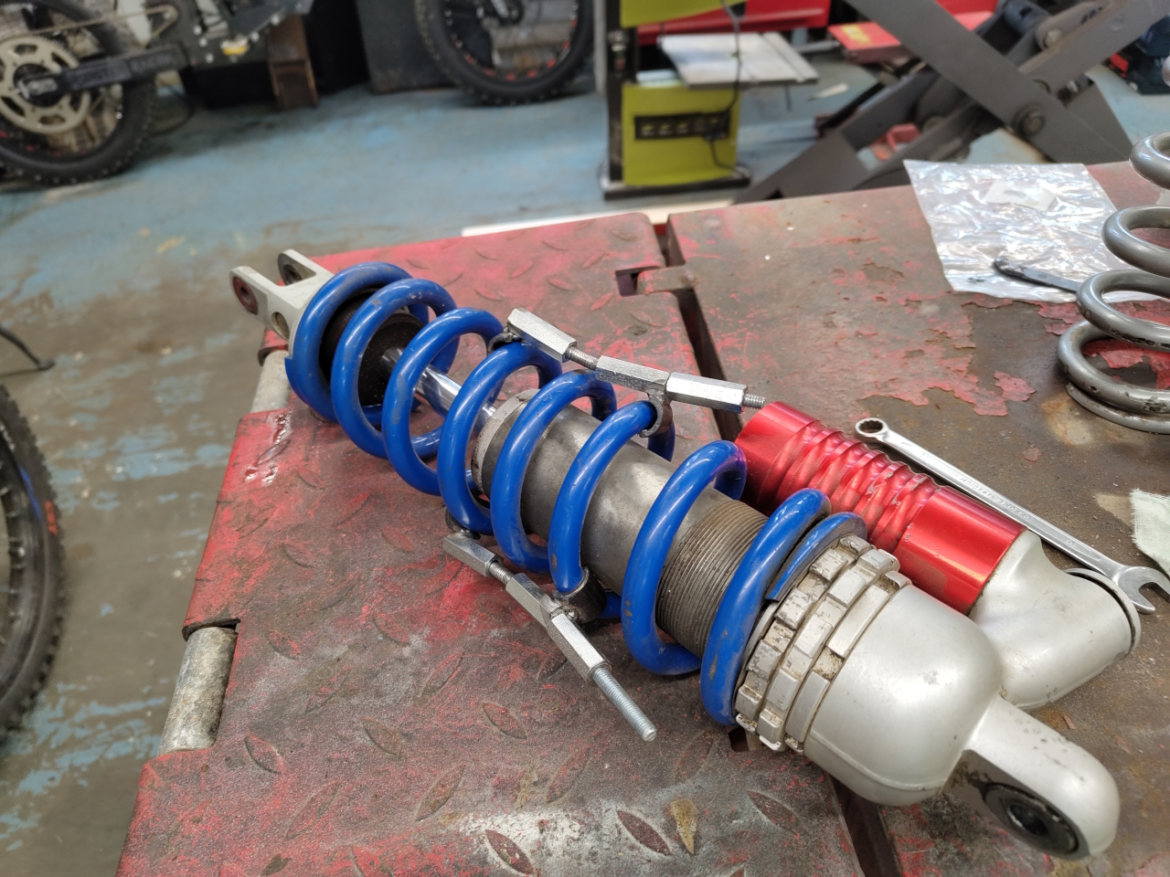
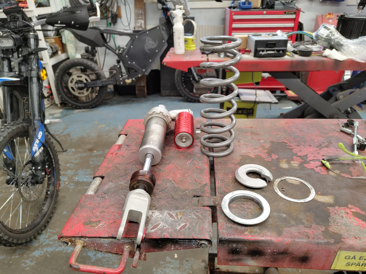
To get the swingarm to sit right I needed the shock absorber and it was fitted with a spring I didn’t like, so the next project was replacing the spring on the shock.
I made tools for this a long time ago and even if they’re a bit bendy they still work just fine. Taking the shock apart, cleaning it up and putting it together took no time at all.
.. and then the shock absorber got back in the frame ..
Since I want to do as few modifications to the original frame as possible I started designing a motor mount that’d mount to the same points as the 250cc motor, ie four bolt holes in the front and the swing axle in the back.
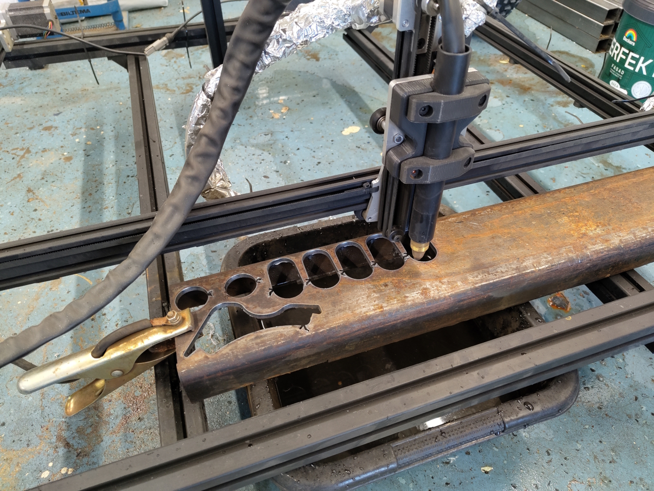
I’ve got some old forks for a tractor that I don’t have, and those are made from 6mm steel tube. Perfect material for a motor mount I thought, and the plasma cut the forks like butter.
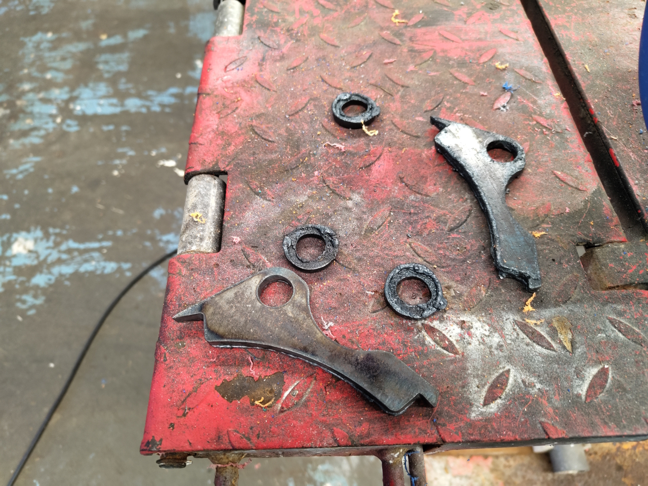
Making some wierd shaped parts to mount the motor to the frame.
.. and some regular shaped parts to weld to some other parts..
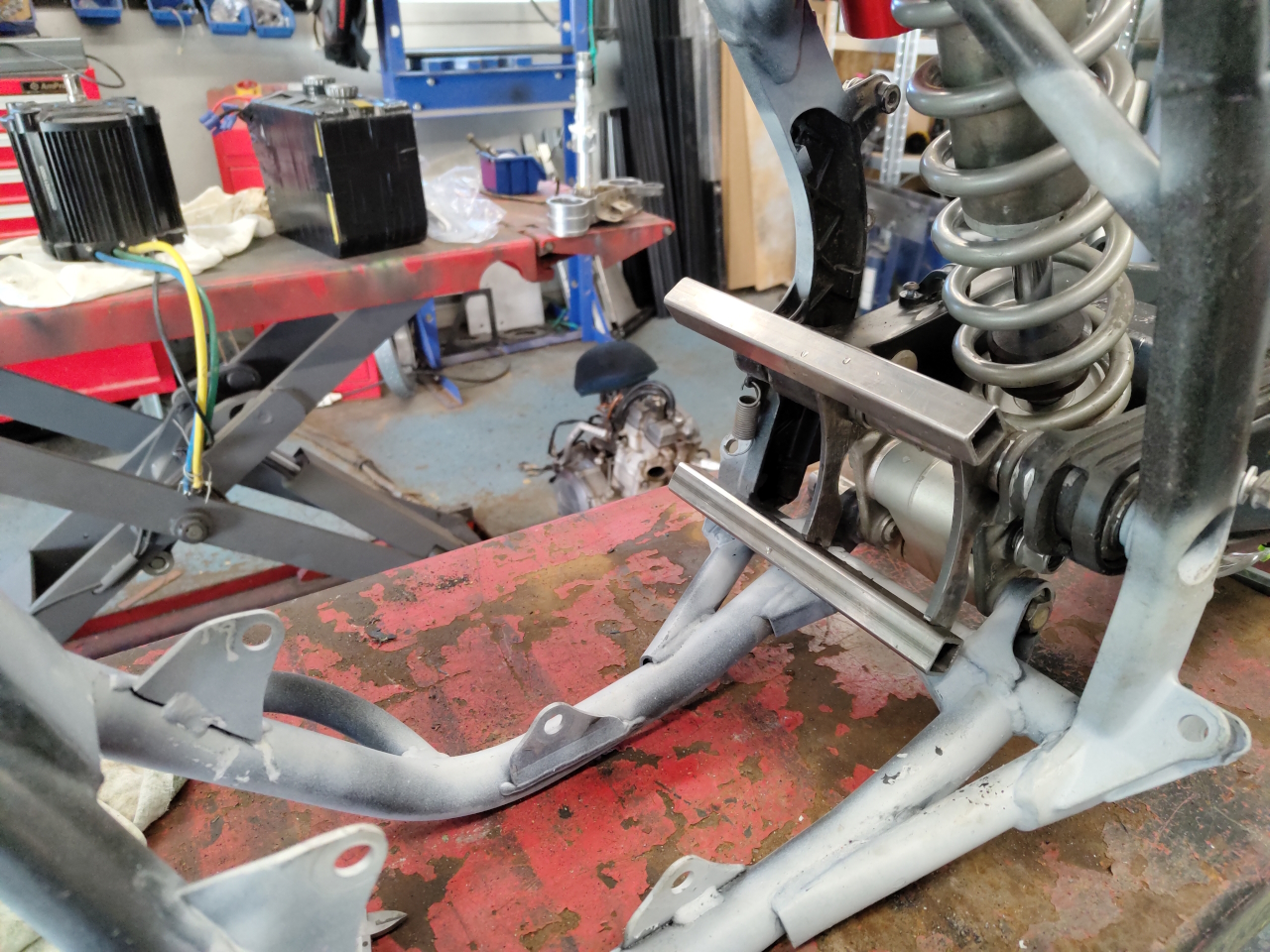
Using 20x2mm square tube I made a mount mockup like this..
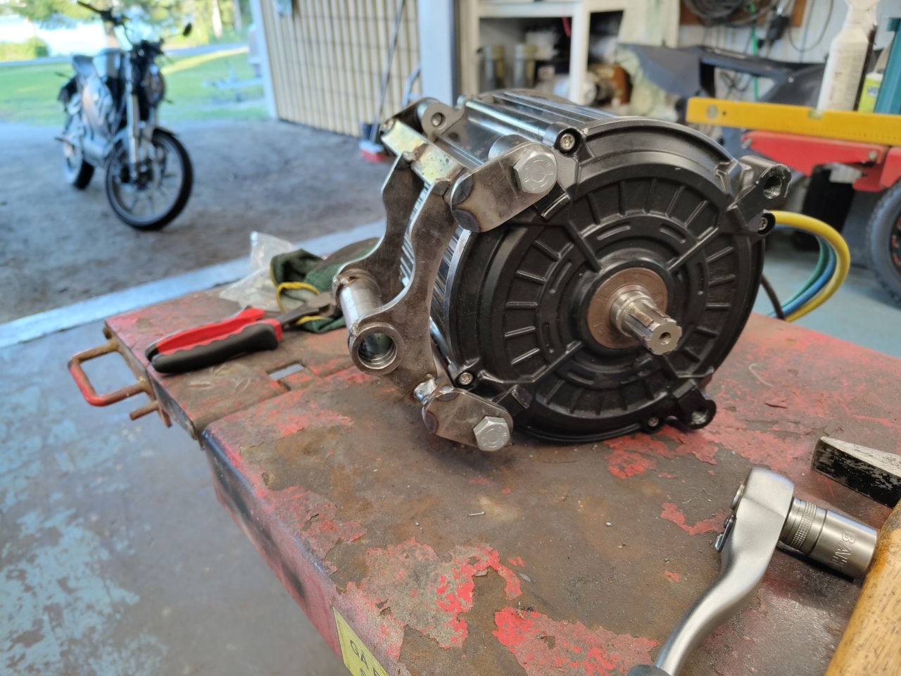
The regular shaped parts were made holy and bolted to the motor..
.. and then used to bolt the motor to the mount ..
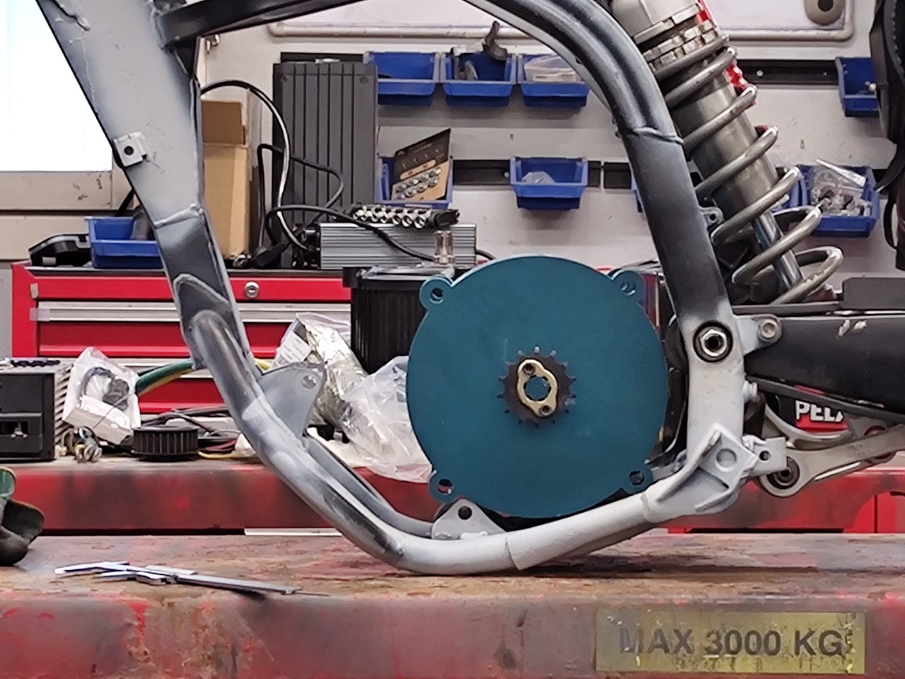
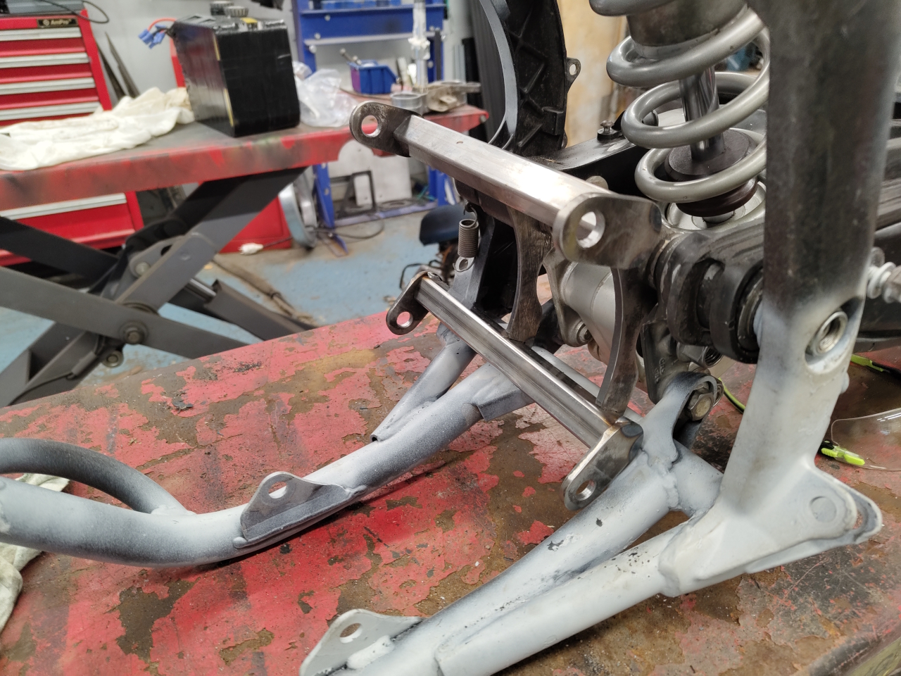
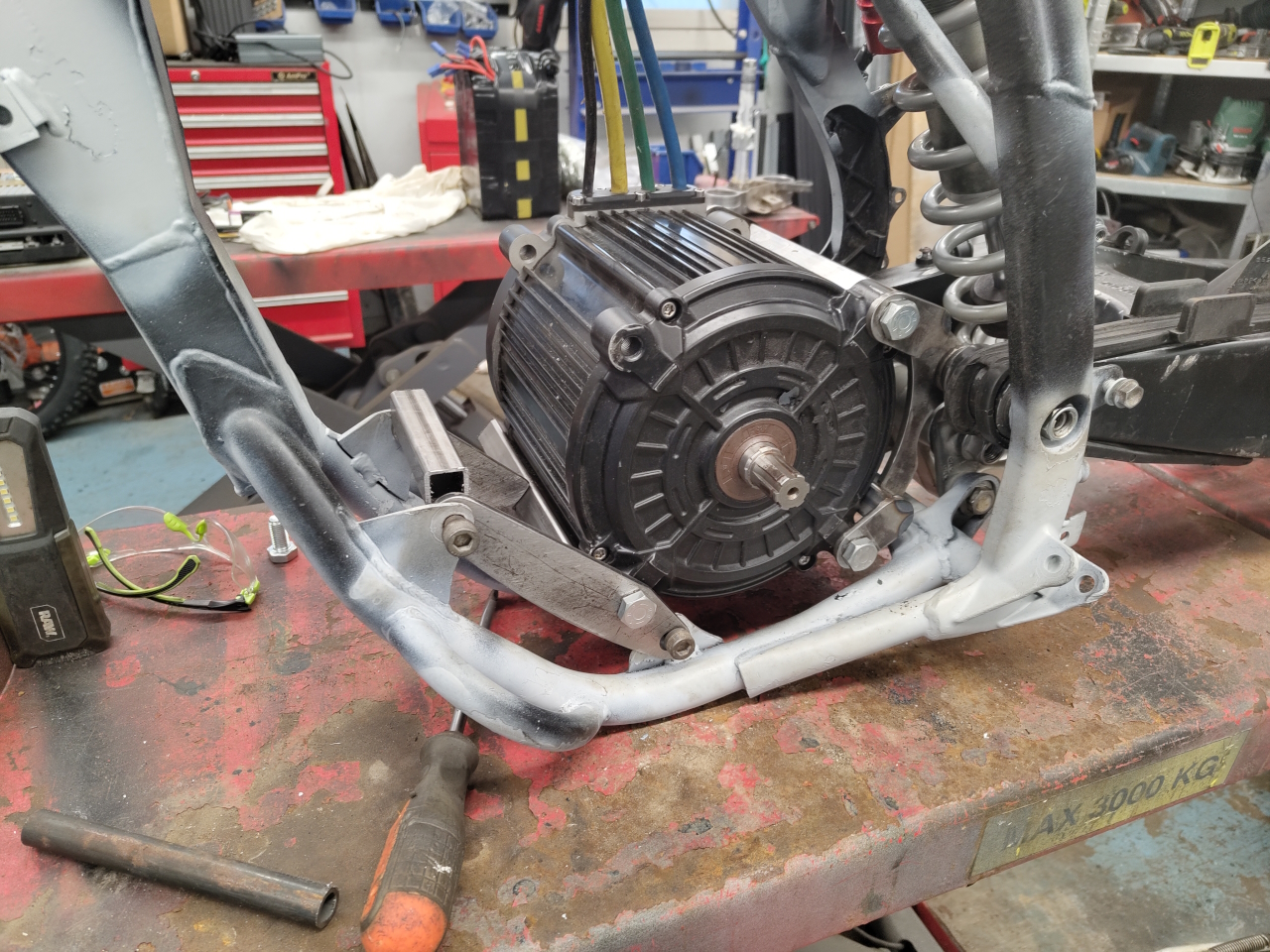
With the mount bolted to the frame I could then mount the motor to design the forward attachment points and make a corresponding bracket..
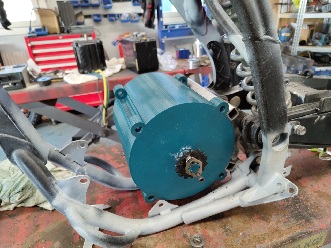
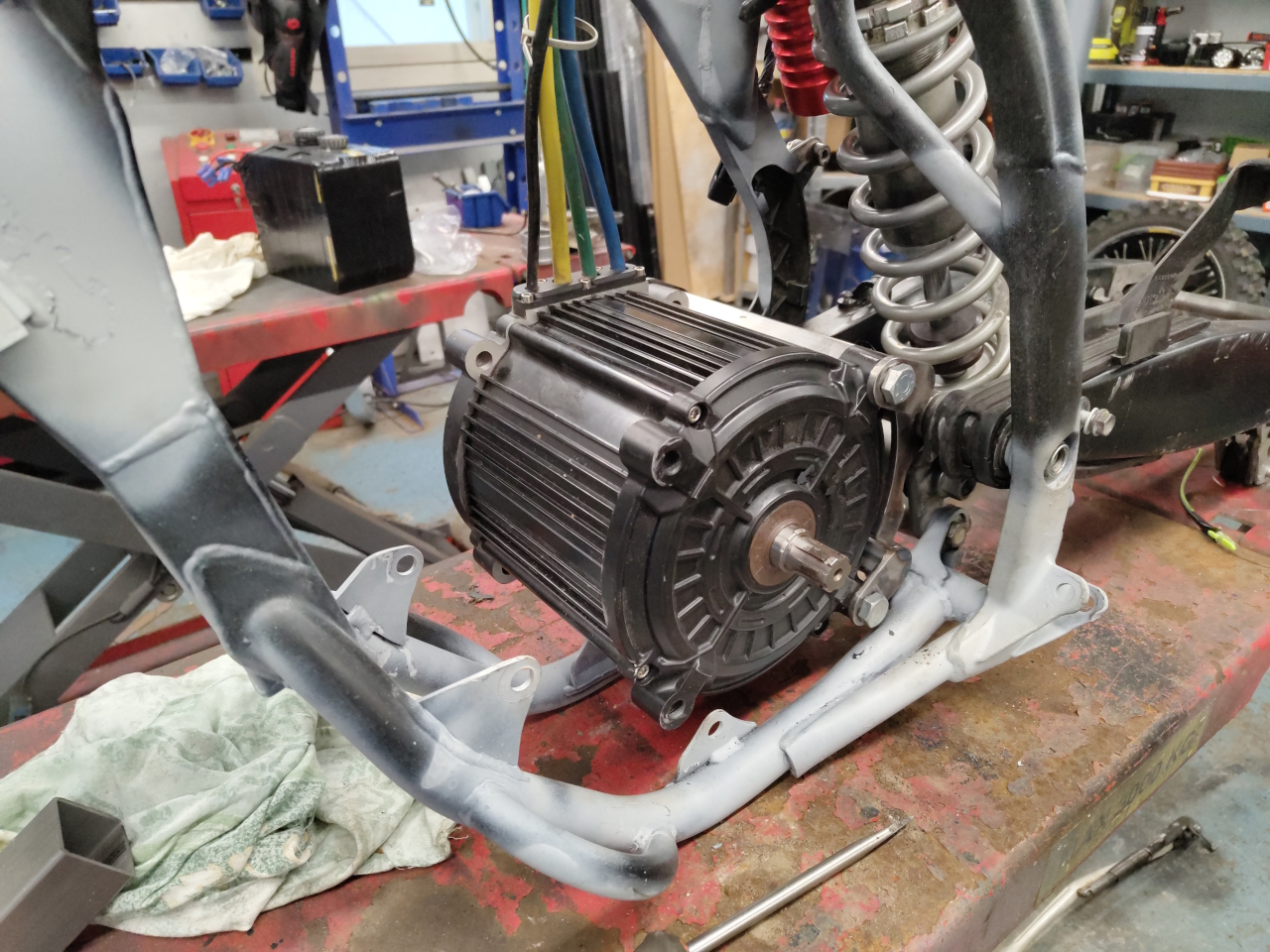
.. and this is what it looks like with the motor mounted to all the attachment points..
Unfortunately the motor is quite wide and the chain runs inside the frame, so in order to not have a two stage transmission with an intermediate shaft I had to position the motor quite far to the right side..
This picture is taken a little bit from the side, so it looks worse than it is.. but yes, it’s noticably heavy to the right side. We’ll see if that’s a problem when riding, if so I’ll have to remedy it somehow.
That’s all I have done so far, next step is to fit the controller in the subframe. Unfortunately the controller is quite a big and heavy piece of equipment and .. well.. it didn’t fit. I’m currently in the process of replacing the steering bearings and putting the front end together. After that I’ll mount the wheels to check what clearance I have to play with and I’ll modify the sub frame to fit the controller after that. Just have to make sure it won’t hit the rear wheel when the suspension bottoms out..
I’ve been thinking of making a youtube video of this build, but with the little time I have for the project it just adds to much work to it all. Please leave a comment if you think I should make a video anyways. I still haven’t gotten around to editing and publishing the previous build I filmed so.. 🙂
And here’s a little video for you to enjoy of my CNC plasma cutting a cover for our chimney.
Now that the motor for the NoGas project has been liberated from the previous conversion the fun is about to begin. But before I can start constructing and building I’ll have to remove everything gas-related from the bike..
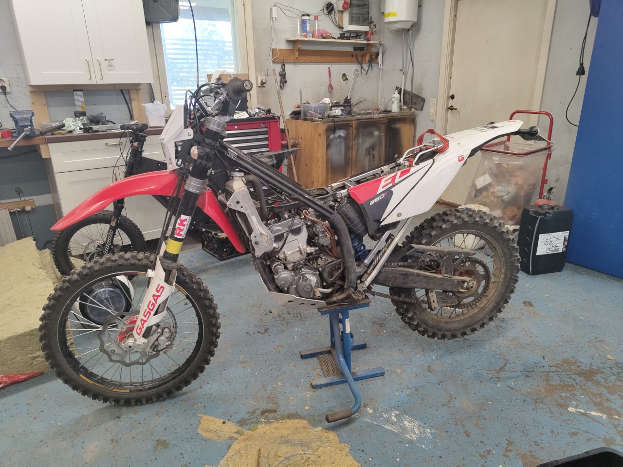
Since I’ve never owned a GasGas before it took a bit of fiddling to get everything off the bike. First to go was the seat and tank..
Then goes the plastic parts..
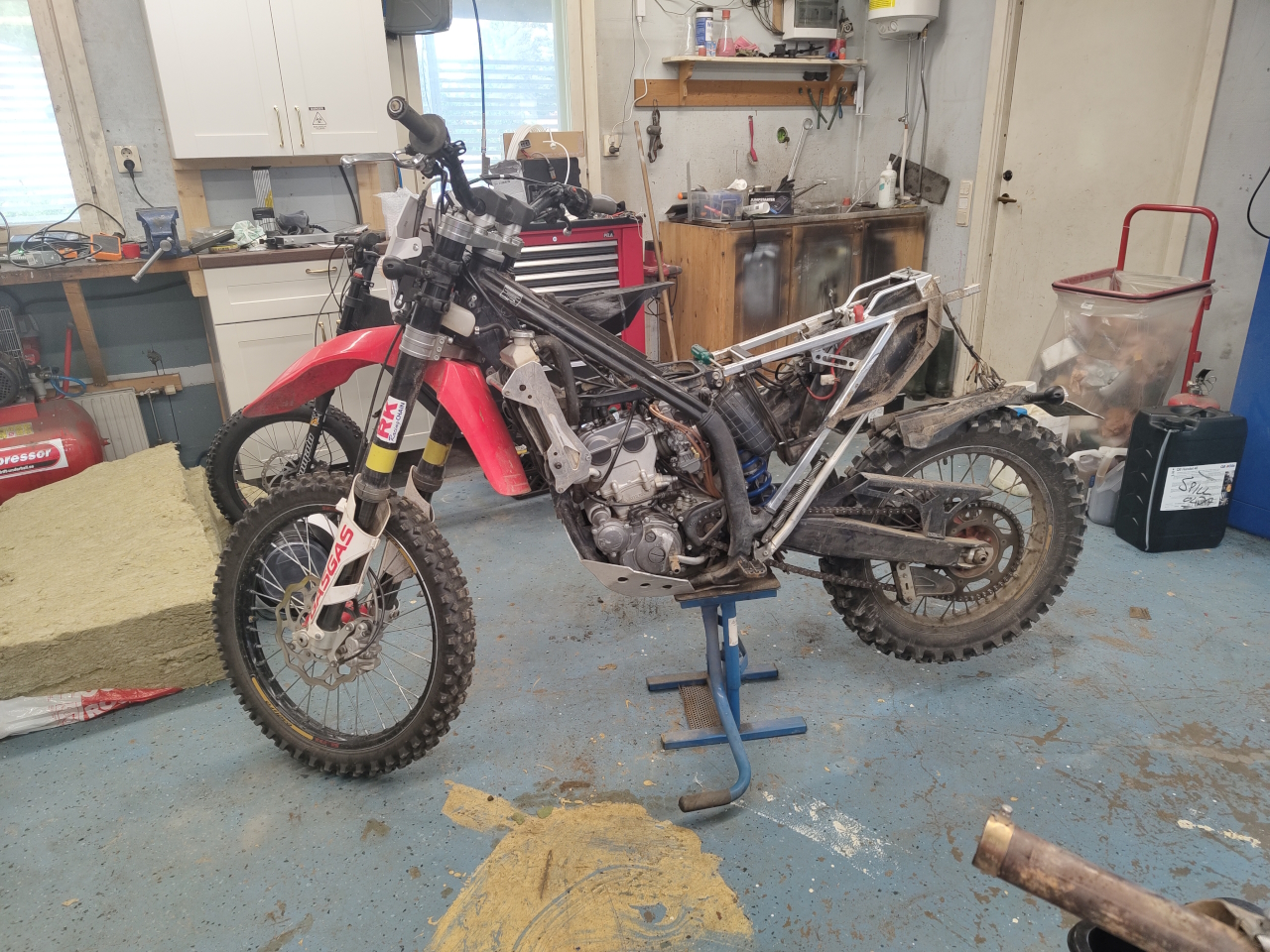
.. to get further the subframe is next on the removal list ..
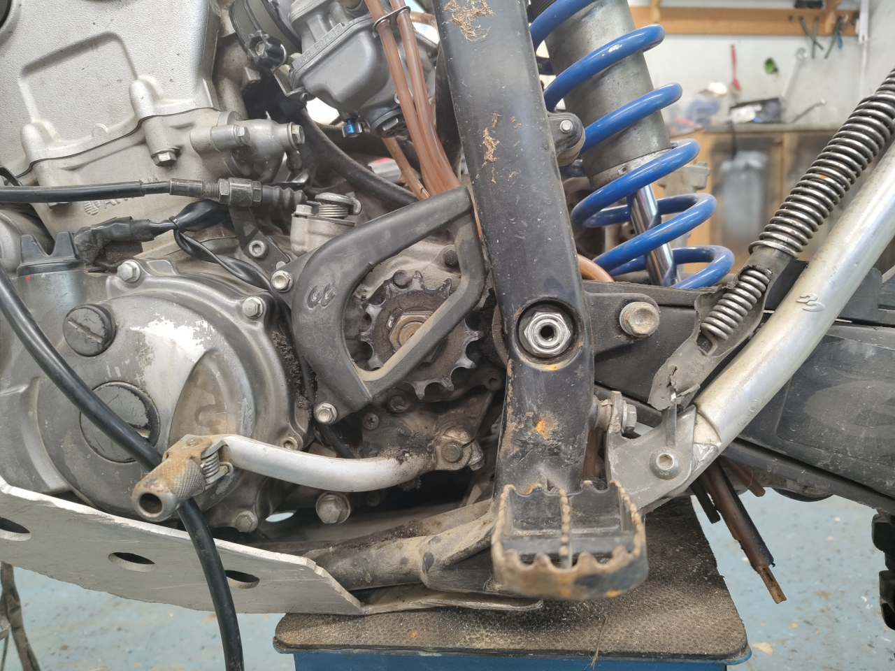
To make the electric motor mount as similar to the original sprocket position I took a picture to try to reference the placement when that’s up. Since the shaft on the electric motor is in the center of the motor I won’t get the sprocket as close to the swing arm without using a transfer shaft, which I don’t want to do.. so..
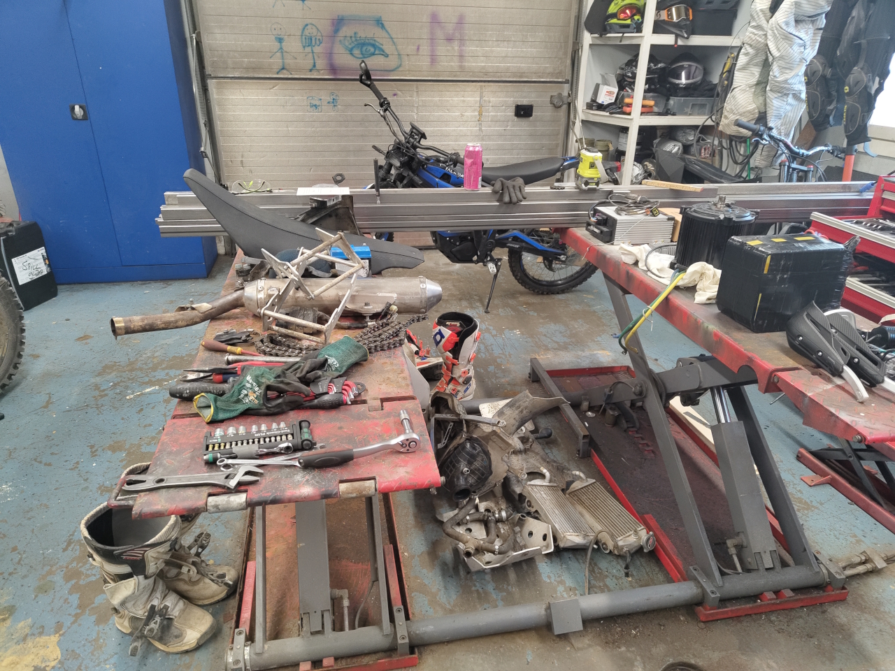
There’s quite a lot of stuff on a bike like this..
.. and I’m just getting started!
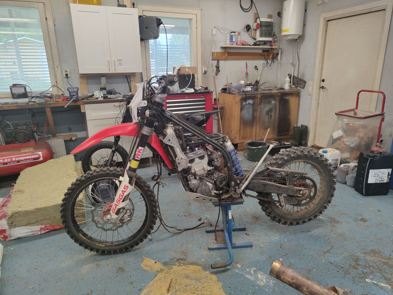
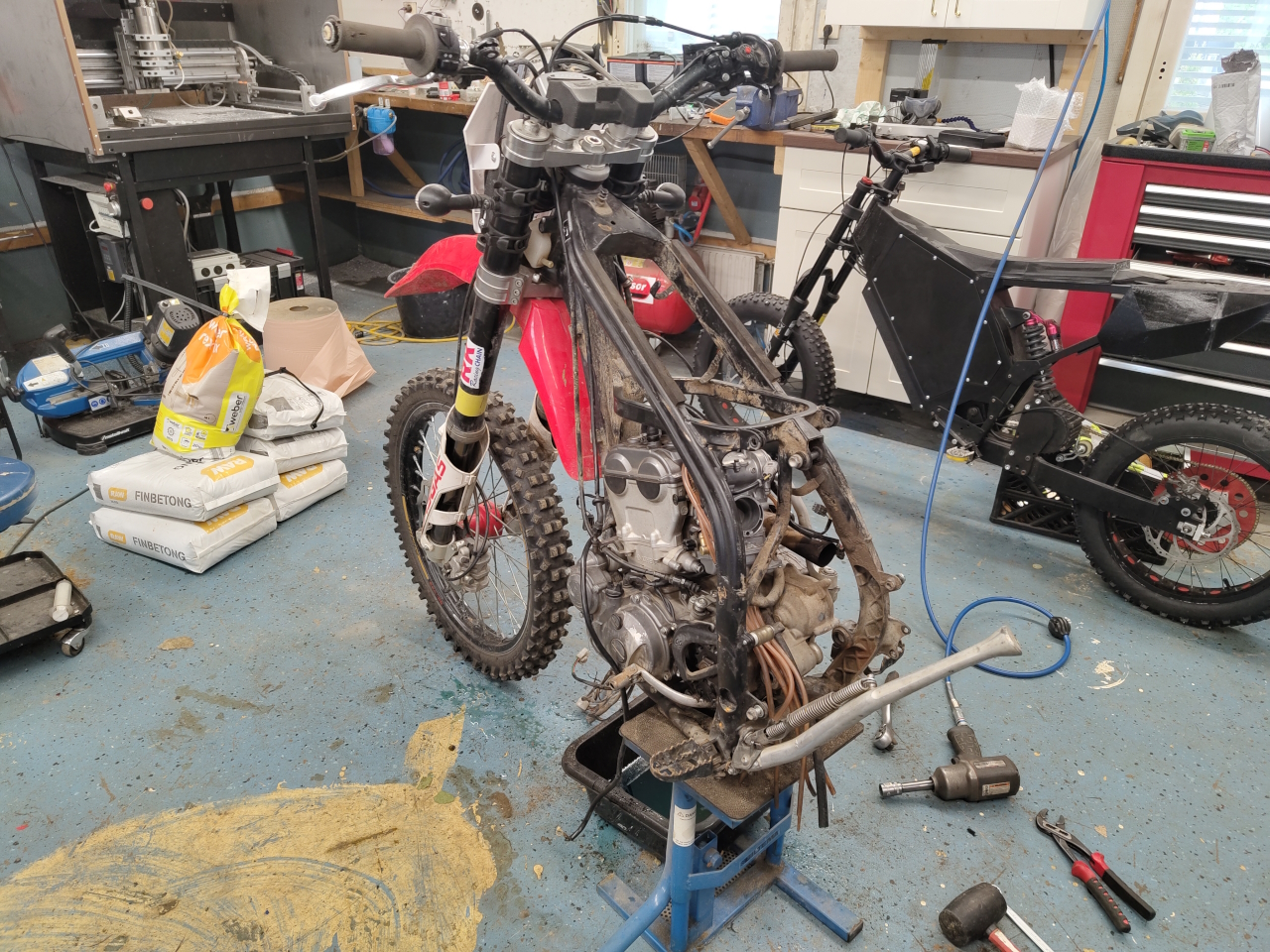
To get to the engine I removed the rear swing and shock absorber..
.. and once that was done there were only two more bolts holding the engine in place..
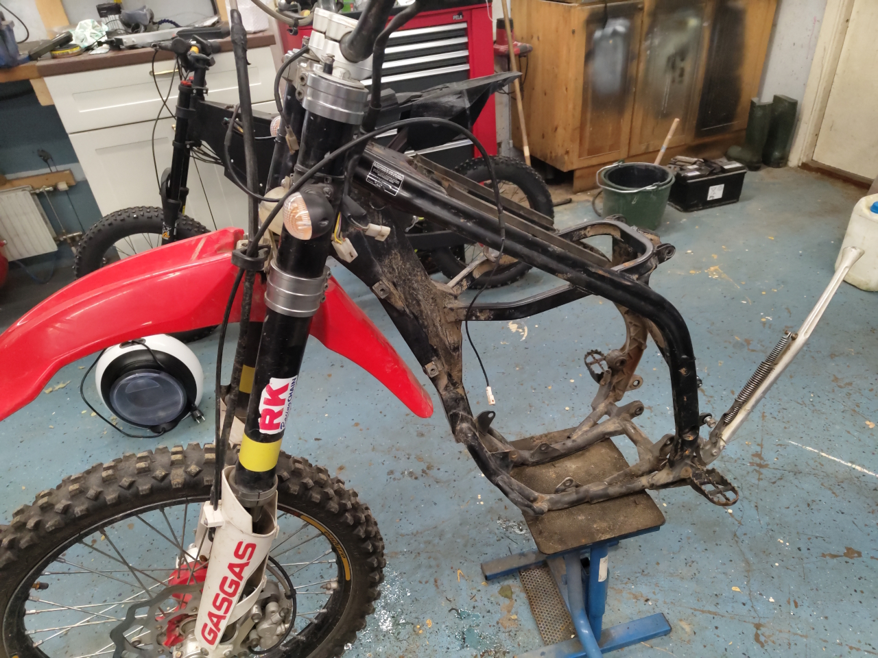
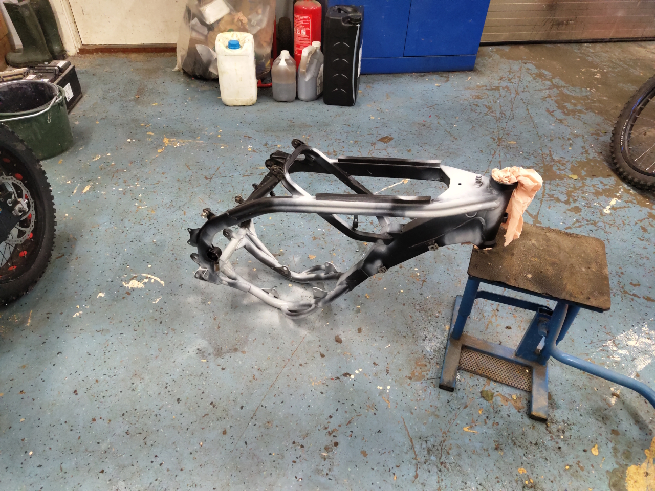
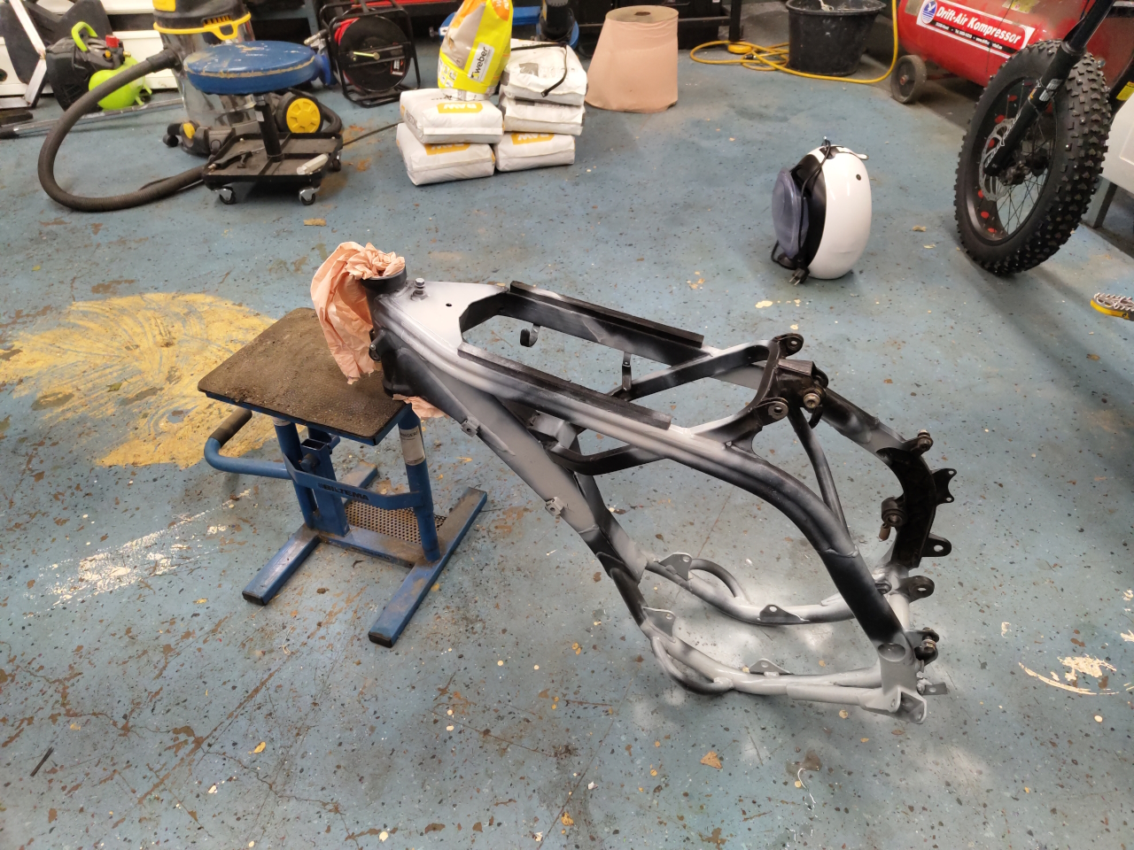
I could’ve stopped here and started making a mount for the QS motor but since the paint on the frame was in quite a bad state and the steering bearings didn’t feel too good I decided to do a proper restoration of the bike while I’m converting it.. so, off with the rest of the stuff..
Now that the frame is naked I sand blasted all the rusty areas and removed all the loose paint. Here I’ve just primed it for paint and this is the state it’ll be in until I’ve got all the welding and modifying done. Then I’ll do a proper paintjob to get it all protected from rust and whatnot..
Since a lot of the stuff I removed was in a pretty bad condition I’m getting a lot of new stuff to go on the bike, like footpegs, levers, bearings and stuff like that. More on that when I get to it. The next step is making a mockup motor since the QS is just too heavy to play around with. Then the manufacturing of mounts will begin. I’m going to try to modify the frame as little as possible but I’m counting on having to make some welding and modifying of the frame to fit the QS.
There’s quite a lot of cleaning still to do, teadious boring work that I won’t write about so next post will be making electrical stuff fit.
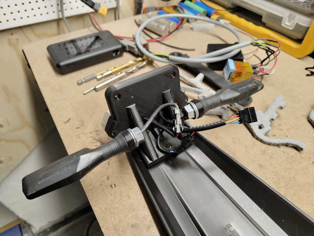
So, after having made the physical conversion with the mounting plate all that was left was the electrical..
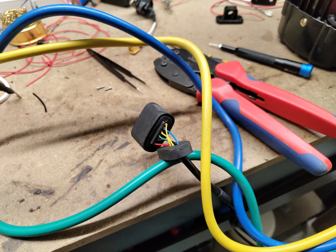
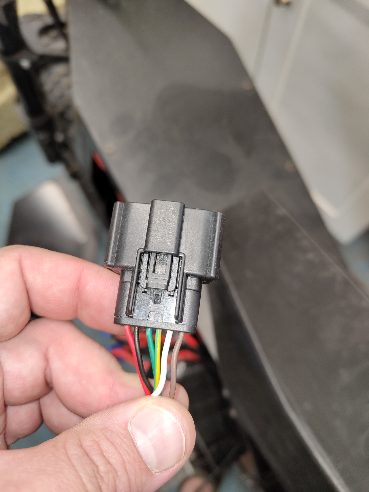
To fit the ASI BAC-series of controllers the hall sensors and thermistor needs a 6-pin molex plug. Those are super hard to come by. Sure, I could buy a complete adapter from the US, but that’d take far too long.. So I 3d-printed a molex plug, the crimp connectors I already had.
A resin printed plug with TPU seals will have to do. It’s pretty sealed and I could fill it with hot glue if needed later. Here I made a mistake though. I used the schematics for the BAC855 controller to deduce the pin numbers for the different hall sensors, and I got it wrong..
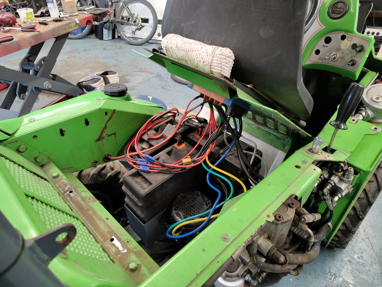
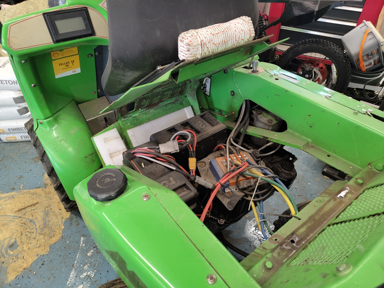
I opted to mount the controller under the seat instead of in the motor well. There it’ll be a bit more protected and it makes for a cleaner installation.. there is however far to much wire in the engine bay..
After having connected everything and made a new battery tray to fit an extra battery pack, the motor didn’t run. I loaded the correct settings file and modified it to fit the Avant, but the motor just jerked and sounded real bad and the controller had warnings about the hall sensors..
One reason I wanted to run the XXL motor with hall sensors was to be able to use the ”Speed” setting on the control algorithm. This would let me choose the RPM and the controller would adjust the current to stay at that RPM no matter the load. However, what I didn’t know..
SO – while having problems with the hall sensors causing the controller not to be able to sense the speed it was running I set speed mode without setting the switching frequency and the bluetooth connection I’m using to configure the controller simply crapped out.
I couldn’t connect to the controller, and the controller wouldn’t run. 😀 *yey*
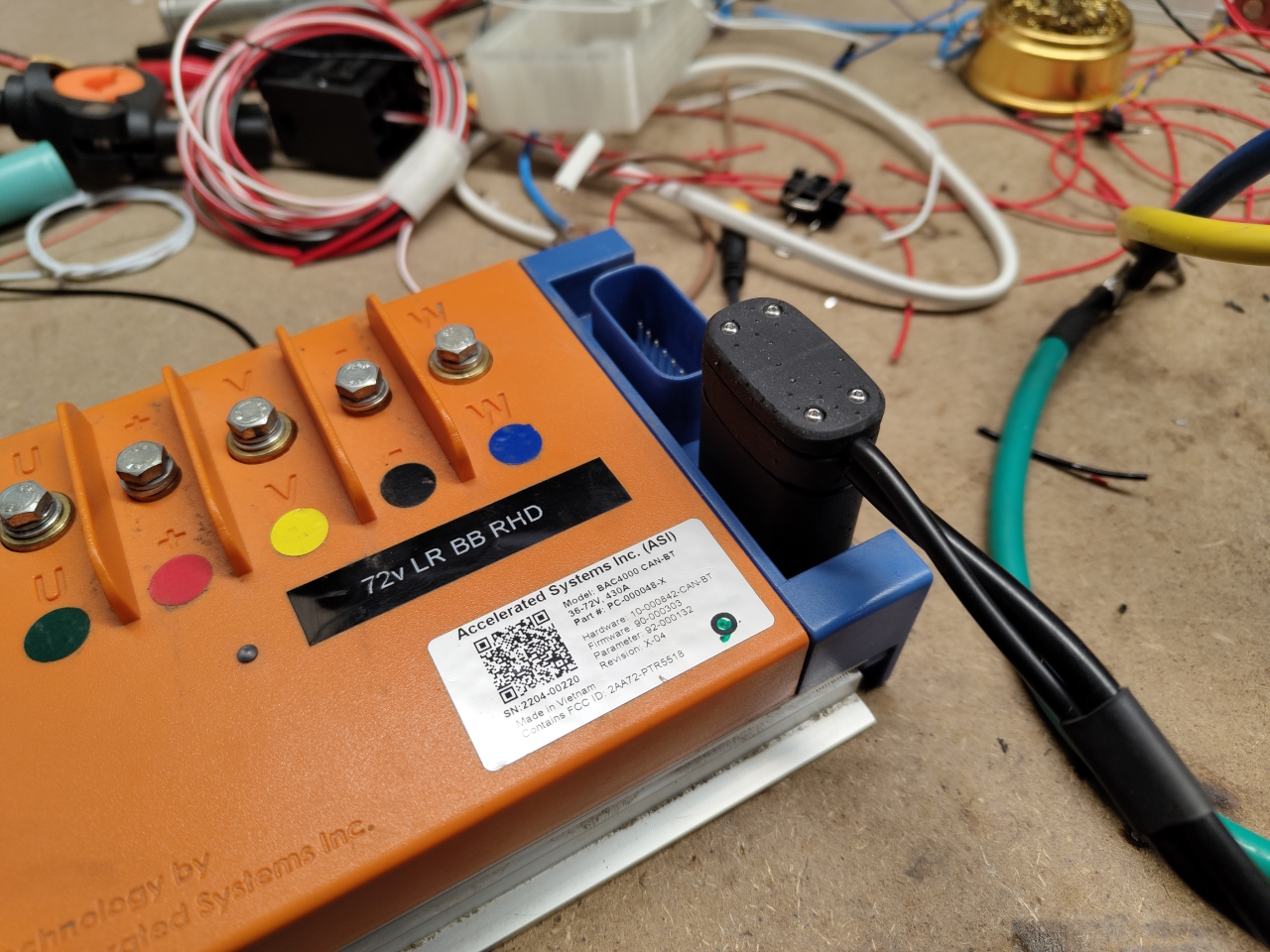
To solve this I had to remove the controller to get it into my office to connect it physically using RS232 to my computer. From there I could, with a lot of help from ”Mr High Voltage” from the High Voltage discord, restore the Switching frequency, the control mode and the bluetooth baud setting. Having measured the hall sensors I figured I had just switched two cables, an easy mistake to make especially when all the other motors I have have custom wire looms that I’ve made myself:
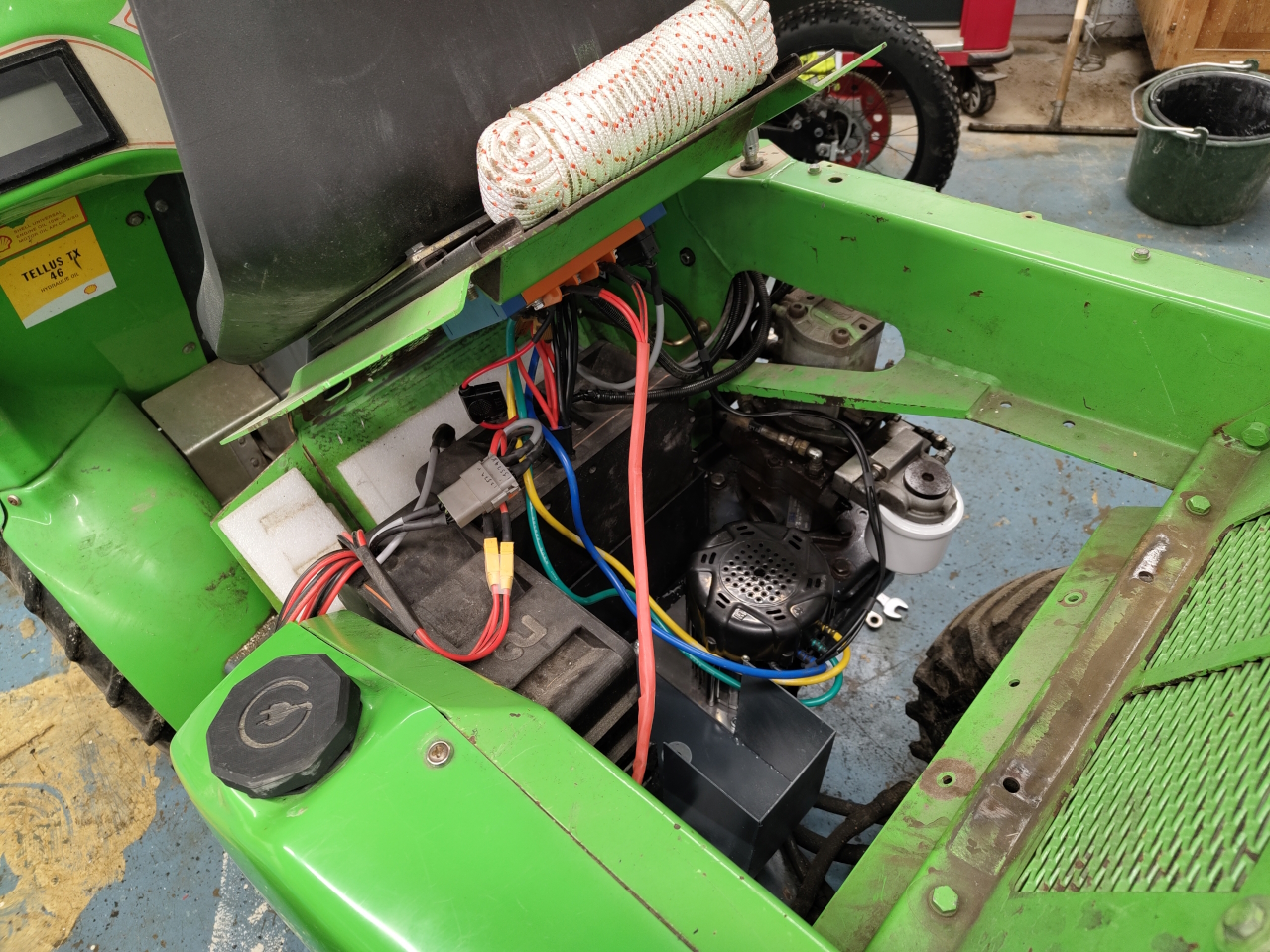
After a bit of rejoicing at the revelation that I hadn’t bricked the controller I put everything back on the Avant.
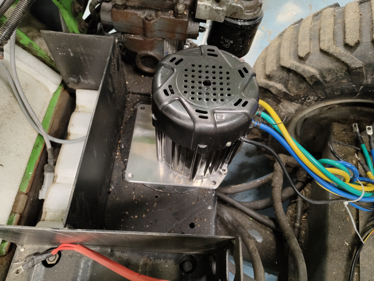
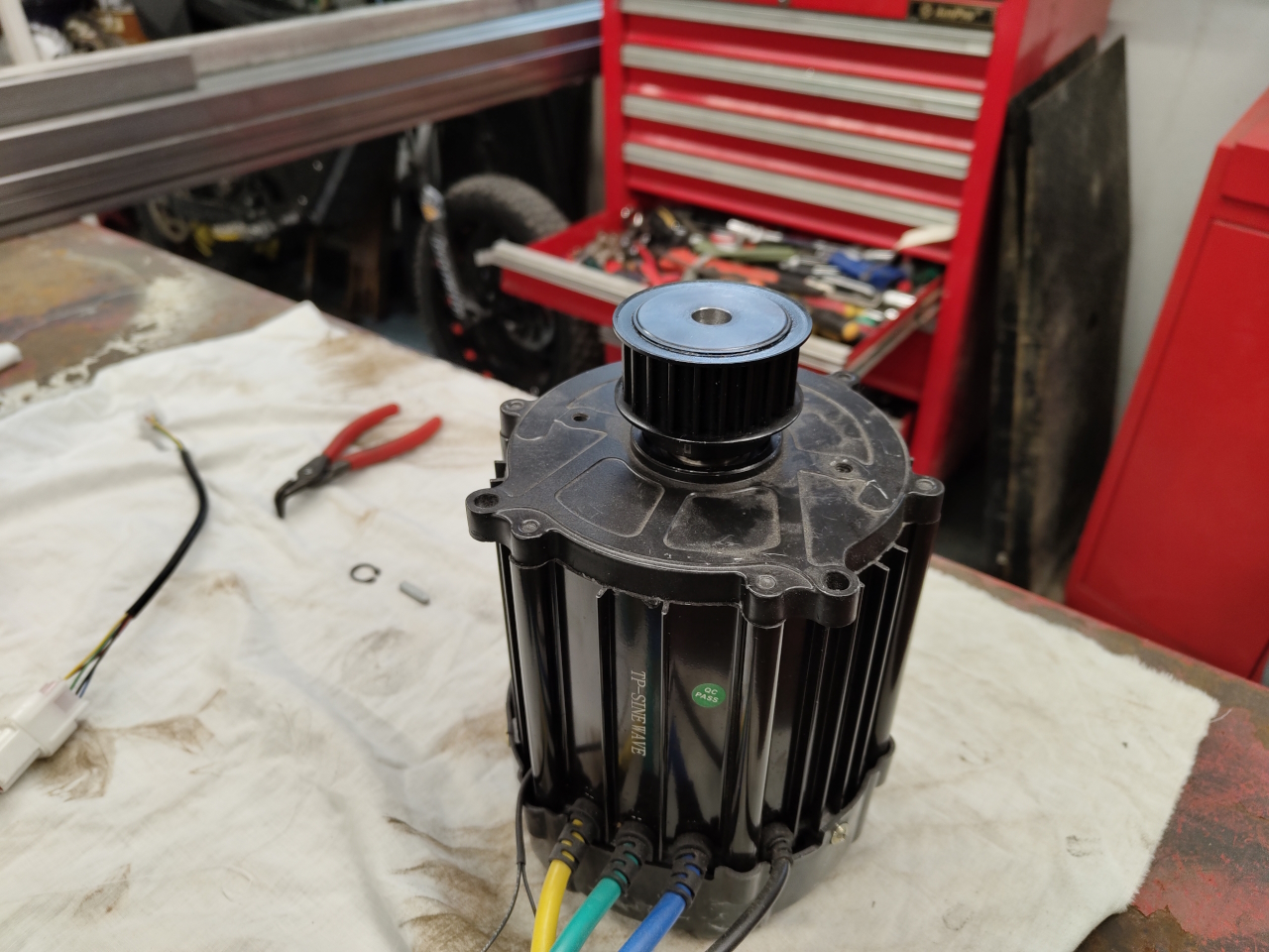
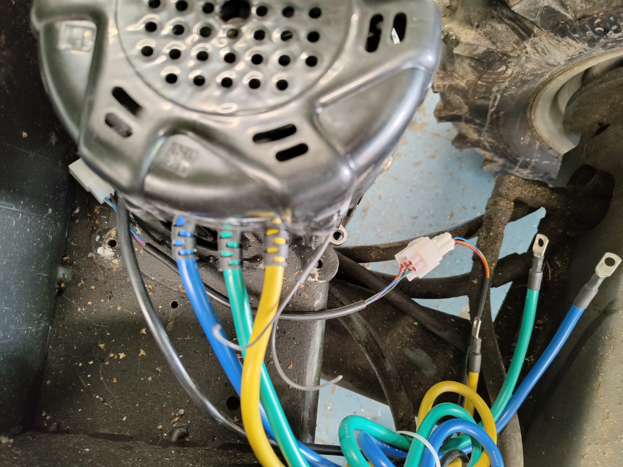
I shortened a few cables and tidied the wiring up as much as I could. Fixed a small leak on the hydraulics, made a washer to fit the belt wheel on the motor as it sat too low and touched the bottom plate of the machine and then the motor just spun like a kitten.
It feels like this motor is a much better fit for the avant. Even with the smaller belt wheel I get more RPM so the machine moves faster. It’s got a cooling fan so it can hopefully stay cool and with room for an extra battery pack I’ll be able to remove the snow from the driveway with volts to spare. 🙂
The only thing I’ve got left to do now is replacing a few joint shafts to get it a little less sloppy, and then the FUN project will start.
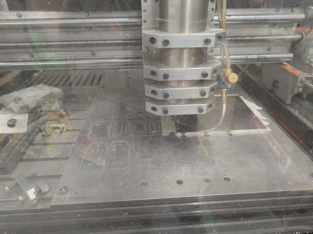
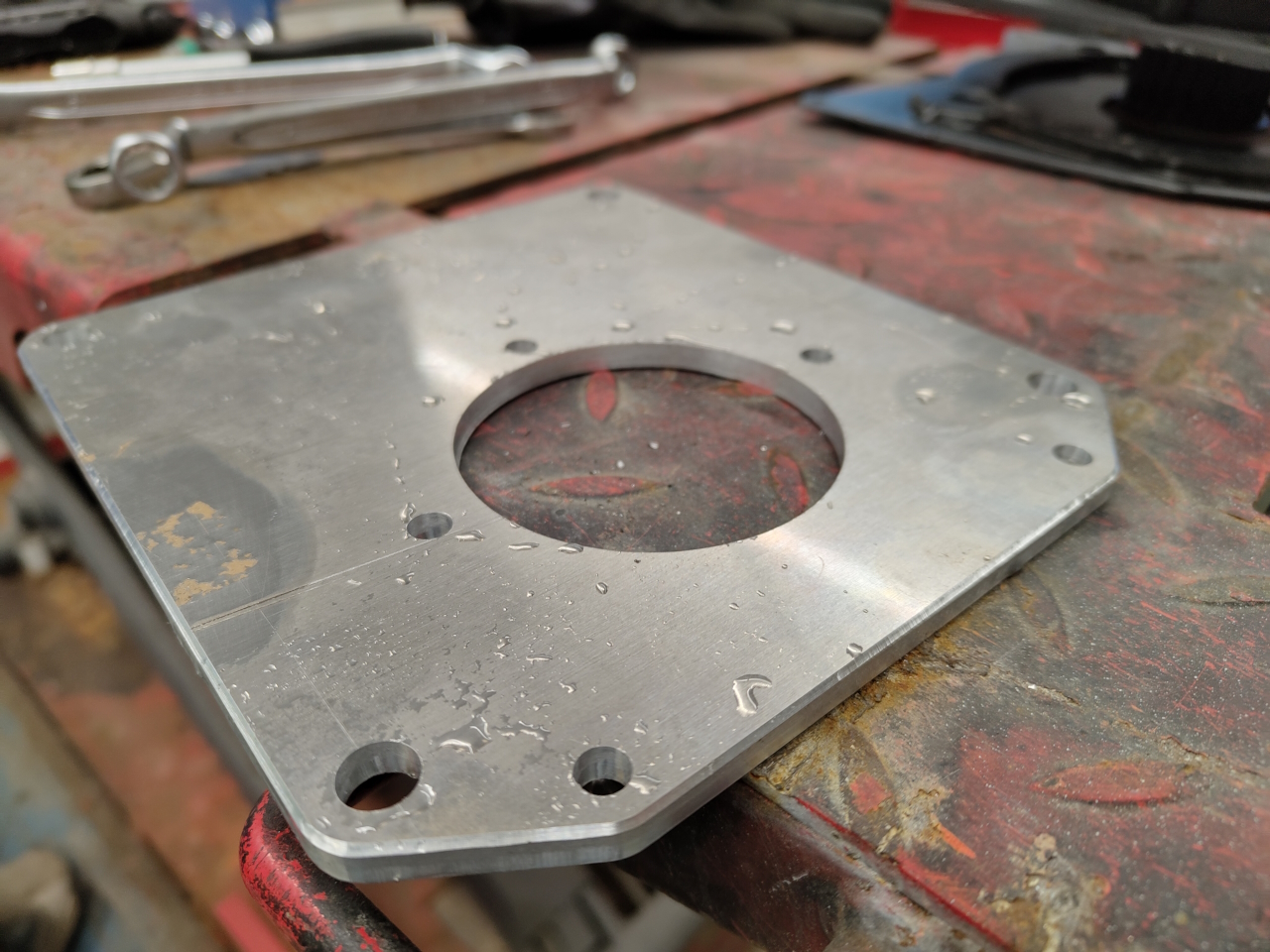
So after spending 5 minutes on the CAD, just as long on the CAM and 20 minutes on the mill I had a new mounting plate for the XXL motor.
I really like the finish of the milled aluminium, with chamfers and all. (It looks better IRL, the camera catches all the scratches and dings)
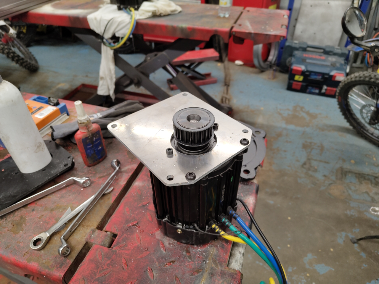
The plate fits the motor perfectly and mounts with 3pcs M6 bolts and 2pcs M8 bolts, holding it all securely in place.
Since the motor is a lot smaller than the QS180 motor I’ll probably be able to fit another battery pack in here. I’ll just have make a tray for the battery that I can bolt to the chassis.
I’ve got the parameters for the BAC4000 controller to run the new motor as well, so in theory I should just need to optimize the parameter file a bit and start the machine up again.. I’ll do a proper oil and filter service first though and replace a lot of the axles in the joints that’s worn out.. And I’ll try to be better at lubricating the joints in the future..
That’s all for this post, just a small update. To be continued..
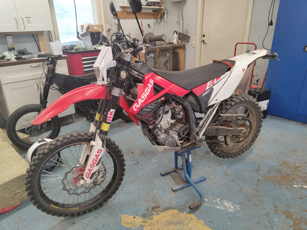
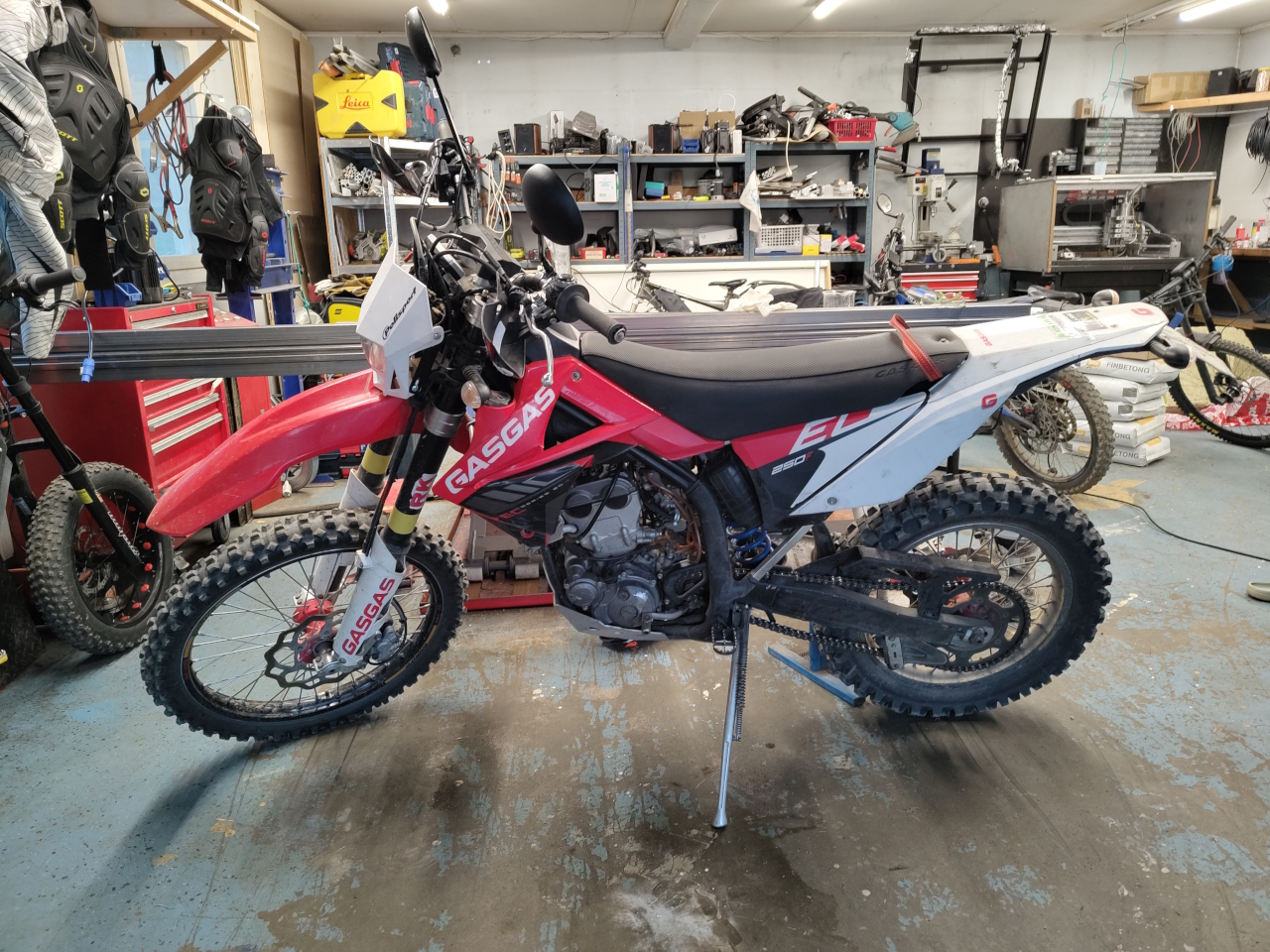
So, since the petrol engine is running lean and I’d rather make the bike electric than spend time calibrating carburetor, I’ll start the project now – a few months earlier than planned.
This is the victim. A 2012 GasGas ec250f with a 290cc kit installed. I bought it just to do the conversion but had planned on running it as a gas-bike this summer as there are a lot of other projects I have to do… but, well.. I can’t say I’m sad to have to push this project up the priority list. 🙂
I’m going to run a QS180 90h motor paired with an APT96800 controller running at 72v. The reason for chosing 72v instead of 96v is that I’ve got quite a few 72v packs already and got the chargers and BMS:es I need to make this work. There’s nothing preventing me from upgrading to 96v in the future if it turns out it’s too dull at 72v. I’ve got a pair of 30Ah batteries that are good for around 300A a piece that I’m going to run in this bike for now. Connected in series they should give quite a lot of *umph*, and last – well, hopefully for a bit of fun at least.
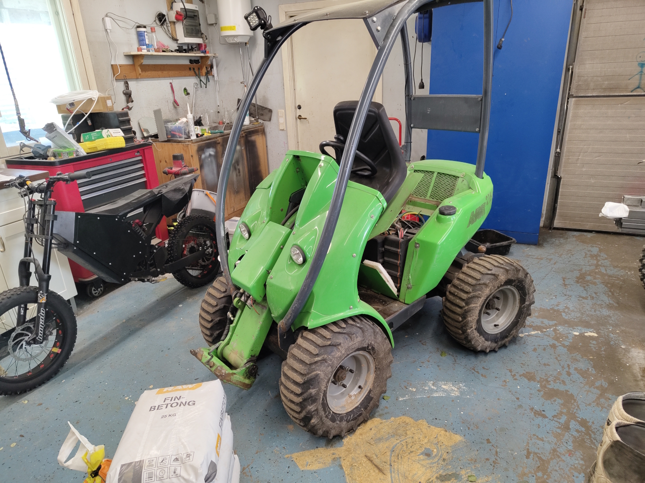
The first hurdle in this project is that the QS motor is here at the moment:
Buried under a lot of stuff in the Avant tractor I converted a few years back. The thing is, I need the Avant to keep running for other projects, so I’ll need to kick off replacing the QS with a LightningRods XXL motor I bought a while back for this purpose.
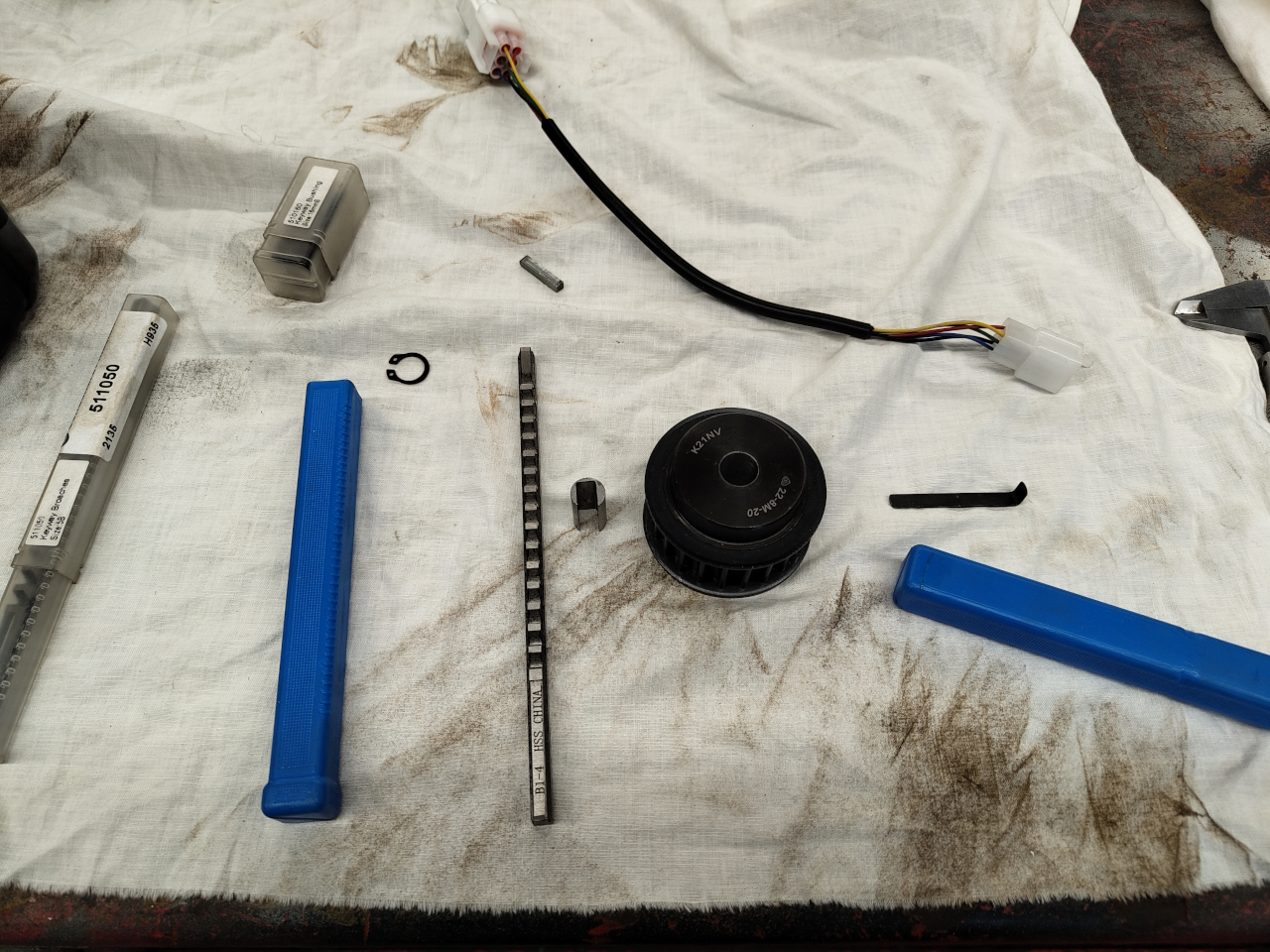
I got a ”special edition” XXL motor with fan cooling that’ll be perfect for the application as it’ll sit stationary under the seat on the Avant. First sub-project will be making the belt wheel fit the axle and keyway of the XXL.
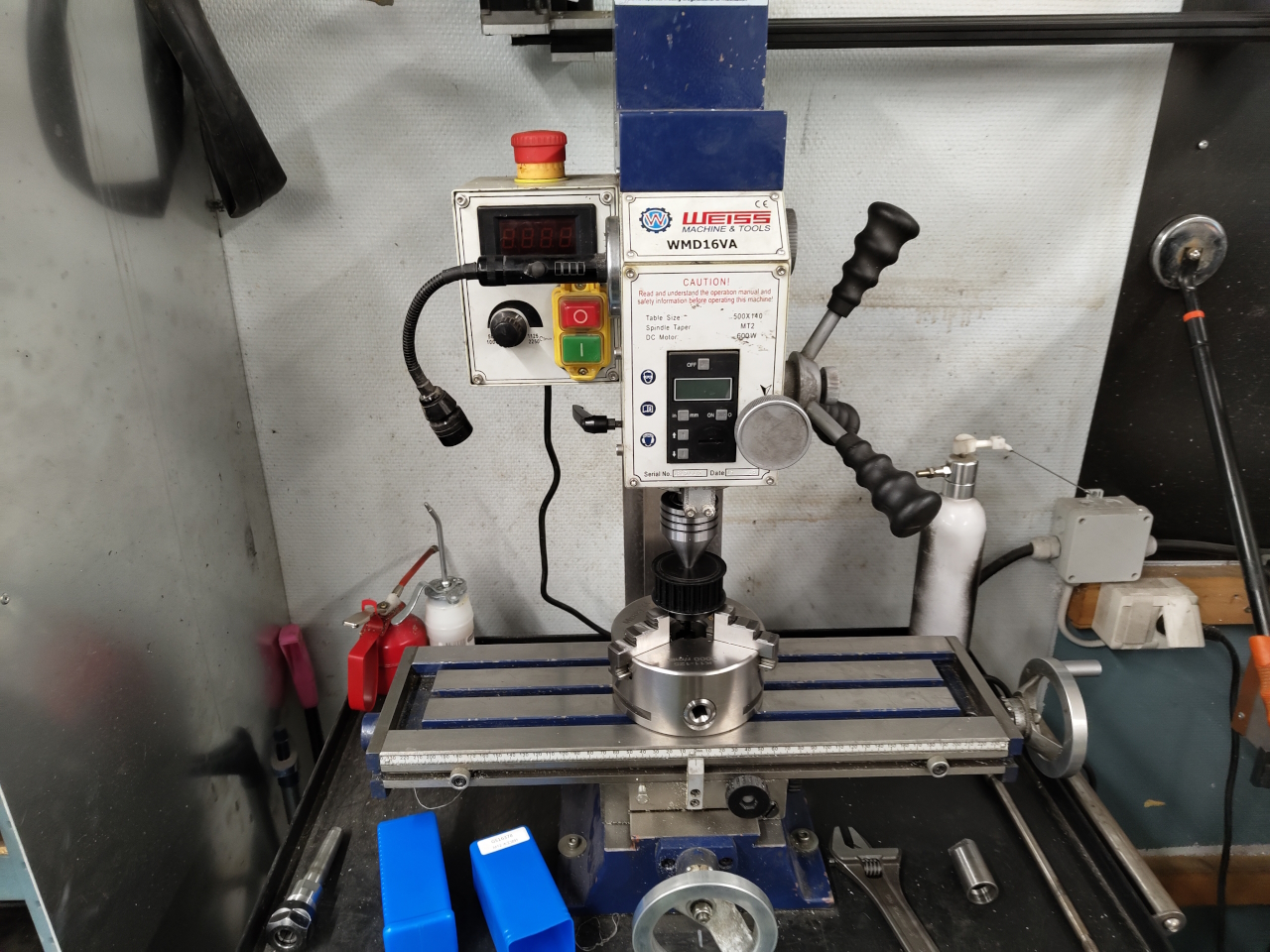
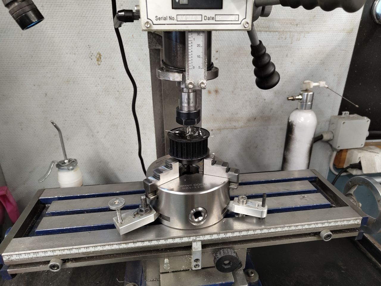
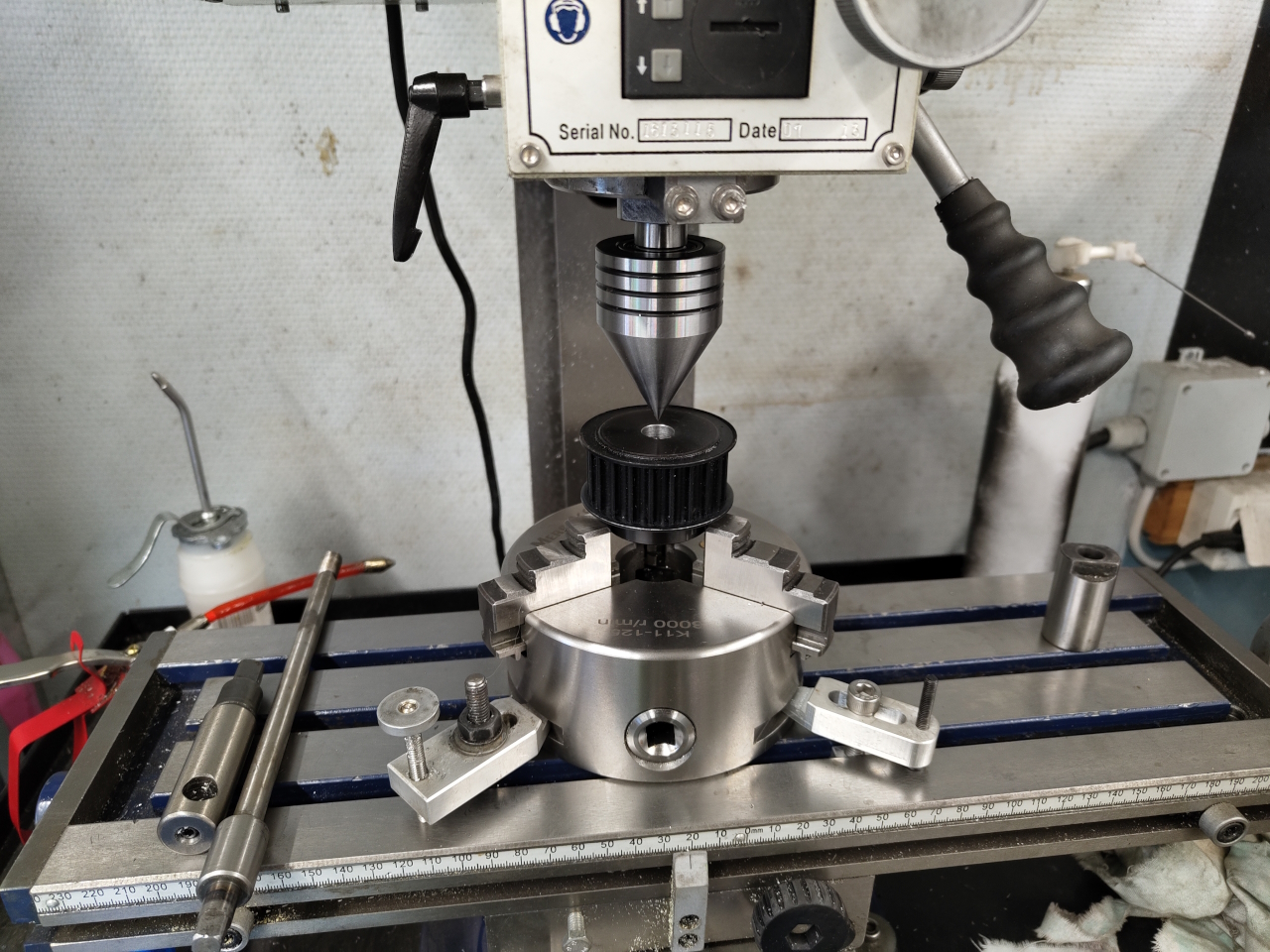
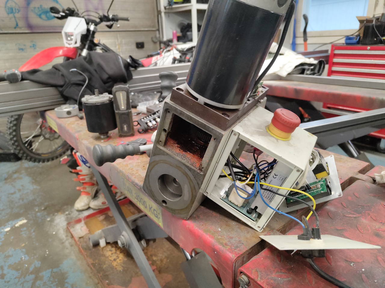
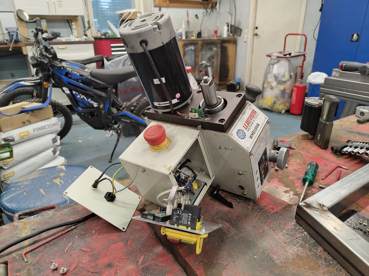
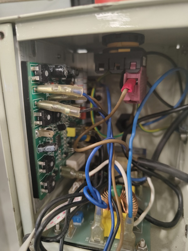
To do this I need the manual mill to be running, and I fried the motor on that one a while back milling unsuitable materials.. In the last post I repaired it with an 800w motor, all that was left to do now was to set it up properly. After a bit of fiddling I got it square enough and set the wheel up in the mill chuck I got just for this purpose, but when doing the first conversion.
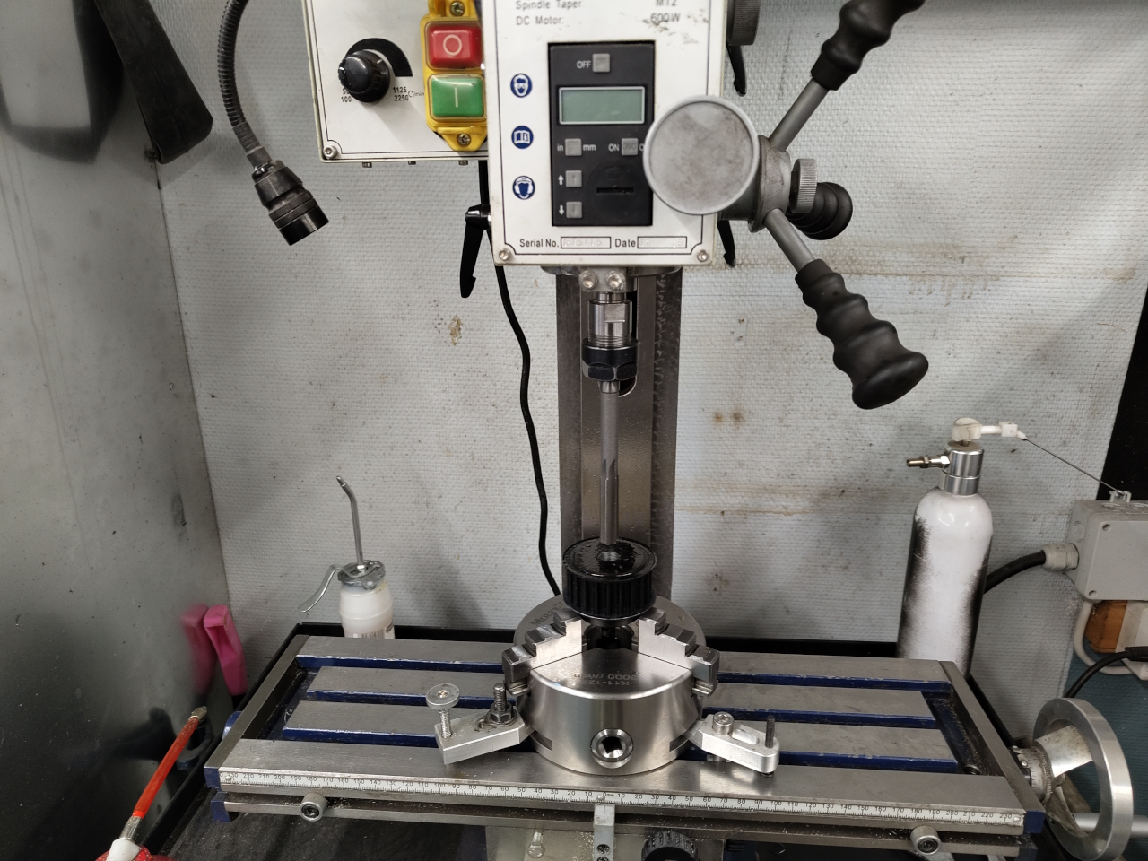
Since I don’t have a DRO on the mill (I’ll have to get one later) I’m using a live center to center the part on the mill. I locked down the table to prevent it from moving and bolted down the chuck while keeping it centered with the quill.
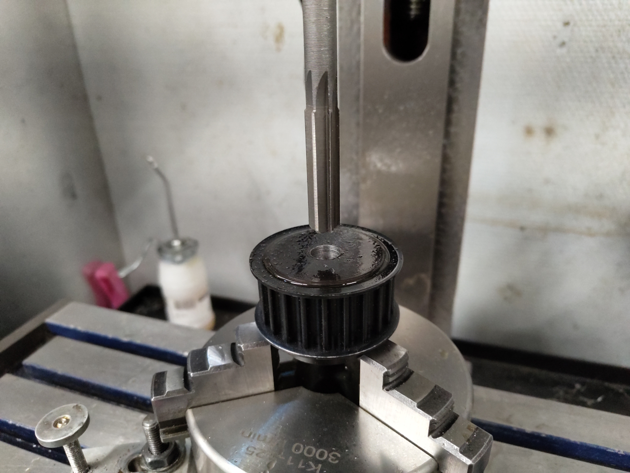
Then all I had to do was drill the hole to just under size and ream the hole to size. 12mm hole for 12mm shaft. Perfect!
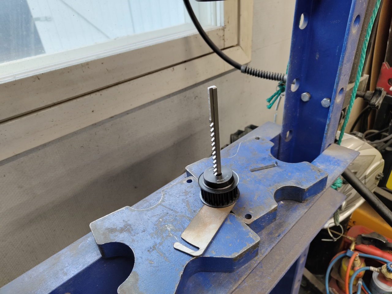
All that was left to do now was the keyway and I’ve got the tools for that.
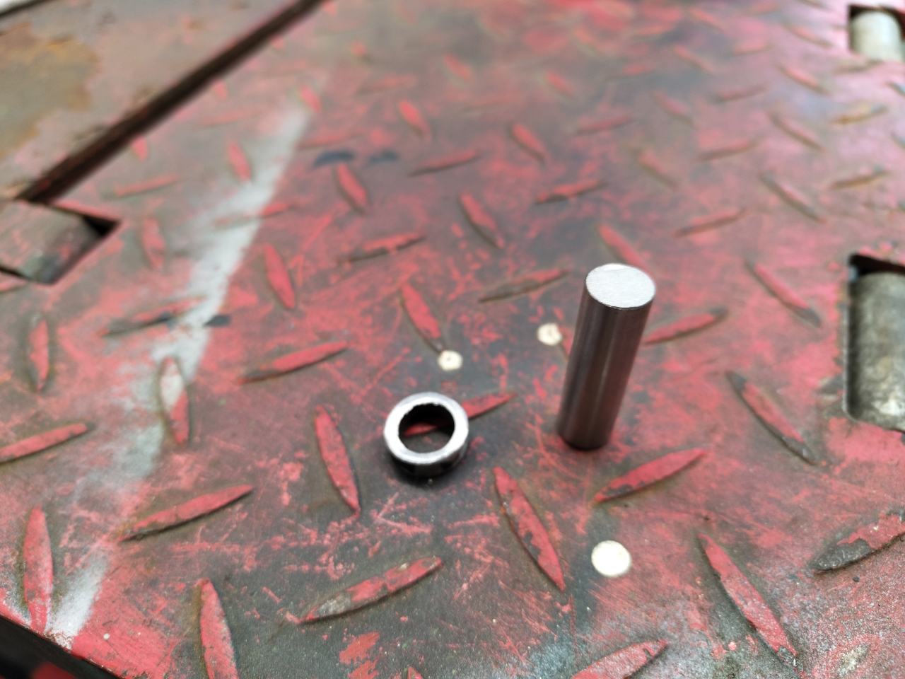
Unfortunately I didn’t have the sleeve for 12mm holes, and I wanted to make the keyway now… so, sub-subproject: Making the sleeve.
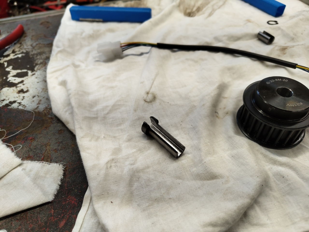
Just had to find a 12mm axle and a tube with 12mm ID. Welded them together and set it up on the mill to make the proper slot.
I don’t know if the reamers are ment for 12mm holes, but there’s not a lot of material left after milling the slot in the sleeve. It’s quite hard to hold on to while taking the last few passes, but it doesn’t have to be perfect.. Good enough is .. good enough.
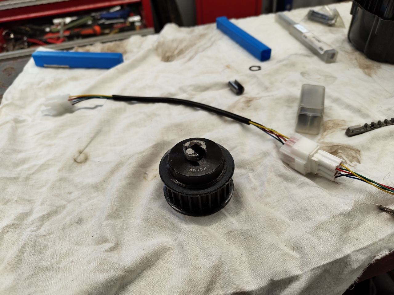
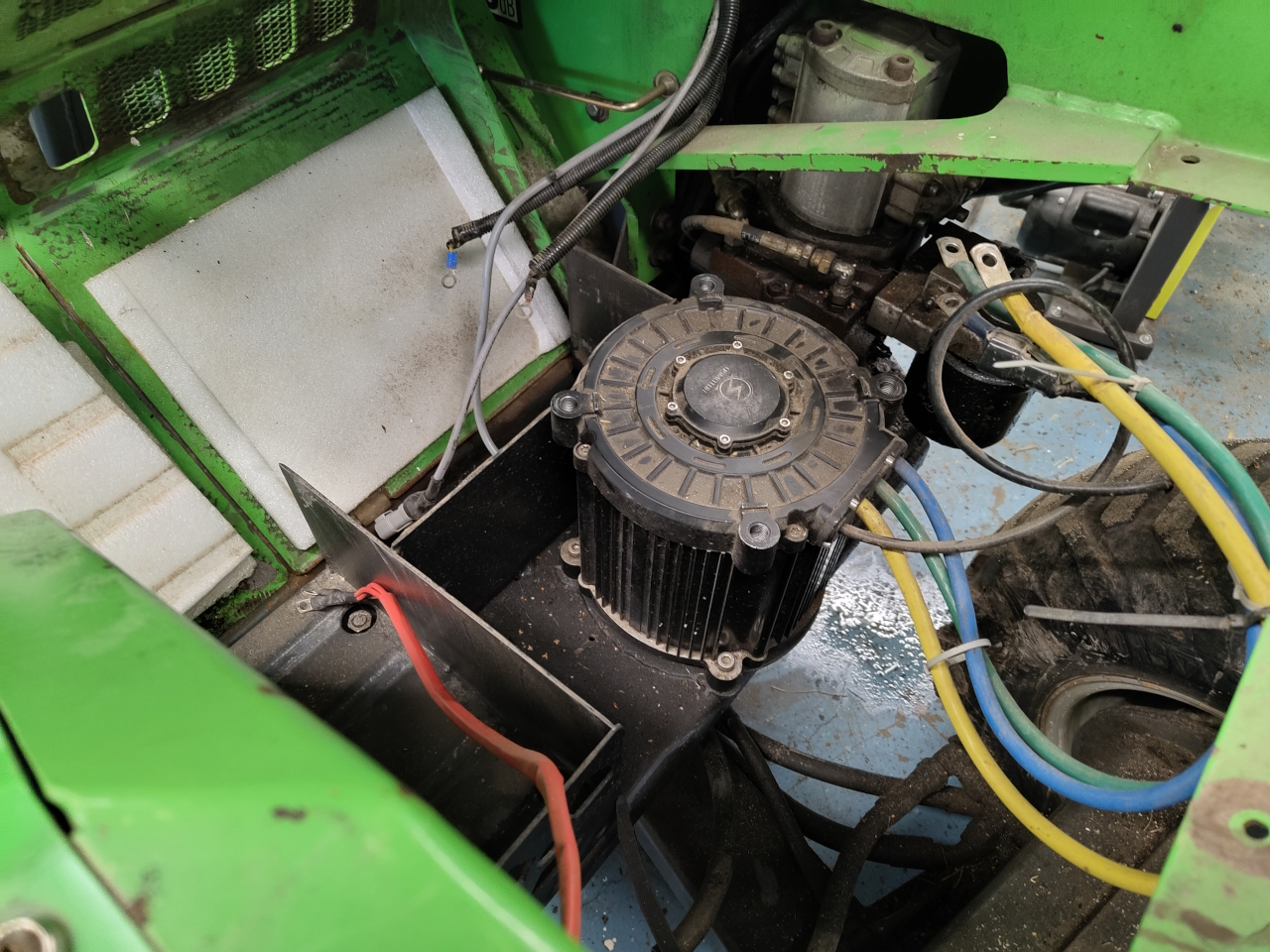
Having made the keyway and made sure the wheel fit on the XXL motor it was time to disect the Avant.
I’ve got to service this machine, it’s been running for years without doing anything to it, and it’s leaking hydraulic fluid from the filter.. That’ll be a later post.
After disconnecting all the wires, removing the battery packs and the controller I could finally get to the motor. Seems I did quite a proper job converting this machine as it’s really servicable. I am however going to try to fit three battery packs instead of the current two when I put it all together to get it running a bit longer. I’ve got two spare packs sitting on a shelf doing nothing constructive at all, better to put one to use.
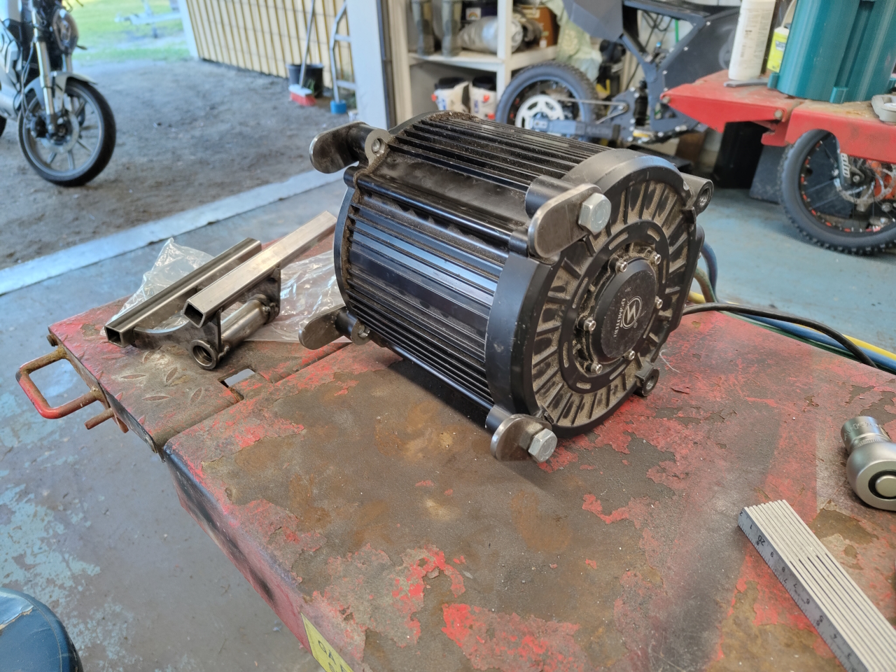
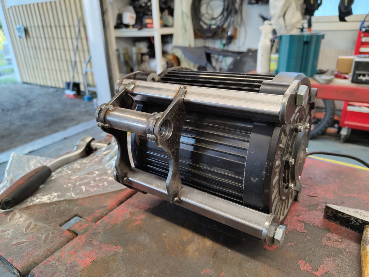
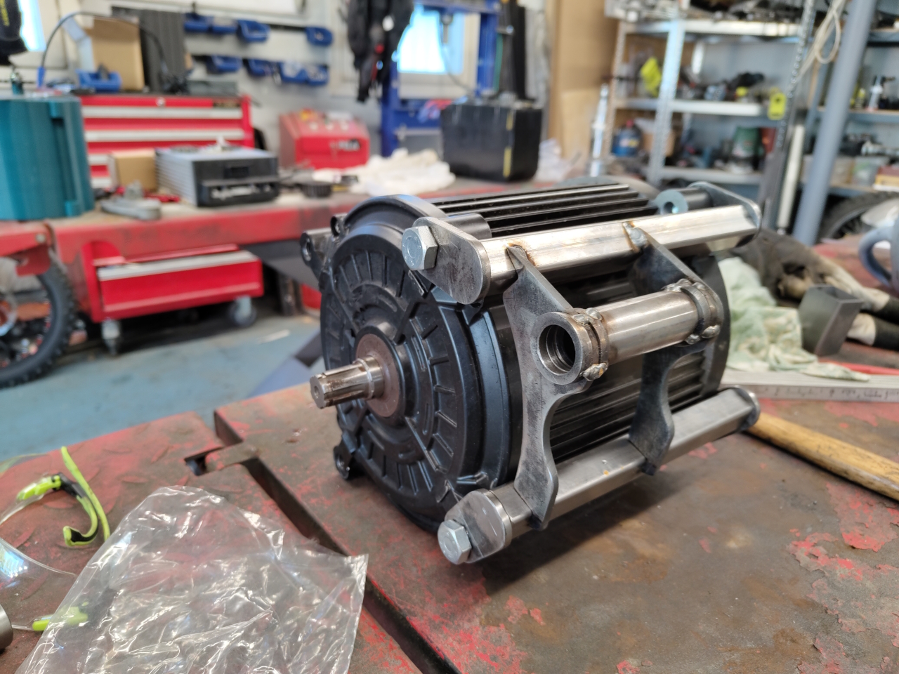
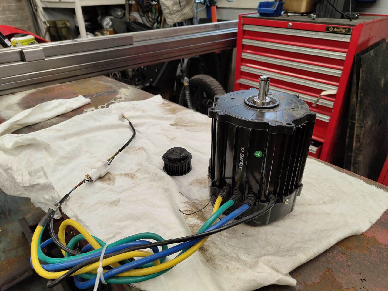
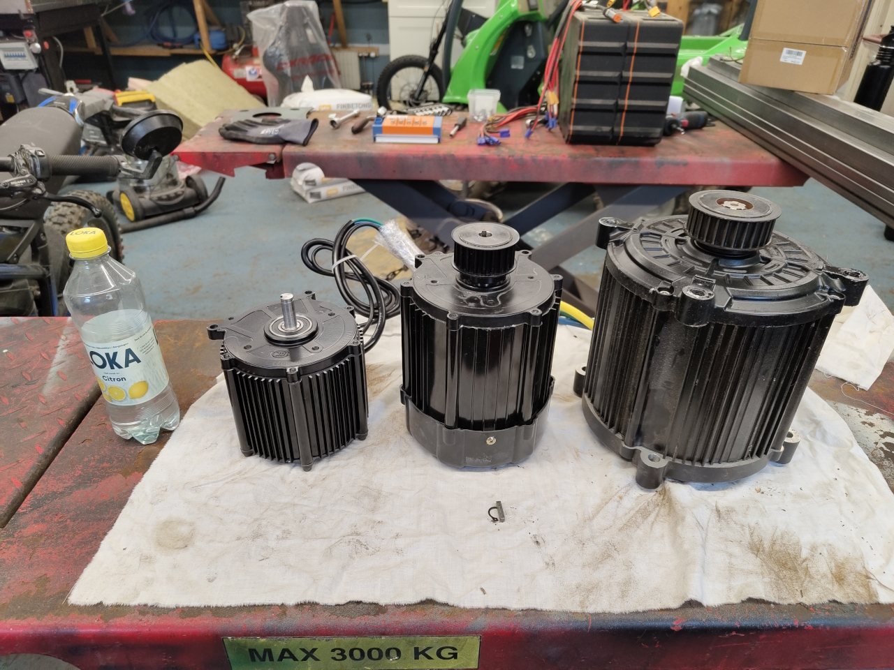
Having removed the QS motor from the Avant I just had to make a size comparison. 🙂
The smallest one here is the Lightning Rods XL motor. It’s a bit more powerful than the BigBlock I’m using on the runbikes, and those do over 110km/h and are insanely powerful.. super fun toys! The XL is supposed to push about 50% more power than the BigBlock..
The center motor is the XXL that’s going into the Avant. I don’t have the proper numbers for it but it’s a larger diameter motor and quite a lot larger overall. That should give quite a lot more torque and it can push quite a lot of power. The Avant averages about 5kW, so this should be plenty.
To the right is the QS180. It’s a proper beast! I’m super stoked to see what that motor can do on a bike!
After having measured the offset of the belt wheel on the axle I set it up on the mill again to bore the hole larger to fit the retaining clip on the motor axle at the right height.
Time for a quick test fit and then CAD to make a conversion plate between the welded QS-motor bolt pattern and the XXL.
The first mockup is on the 3D-printer right now. After test fitting to see how it fits I’ll mill it from aluminium..
As usual in busy times there’s been some time since this blog got updated.. It’s not that nothing’s going on, more so that there’s nothing interesting happening worth writing about.
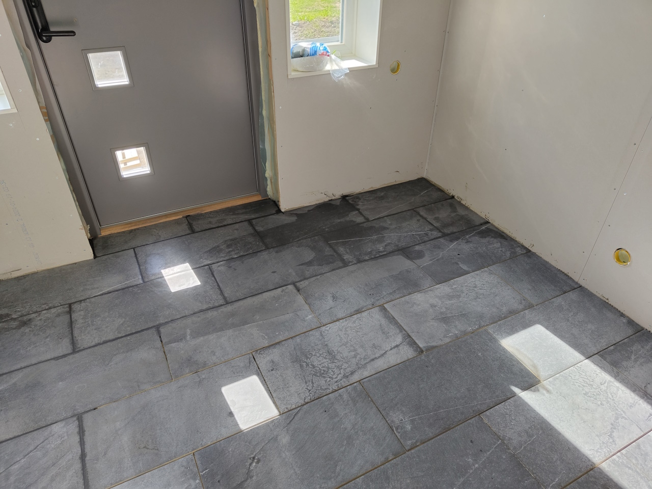
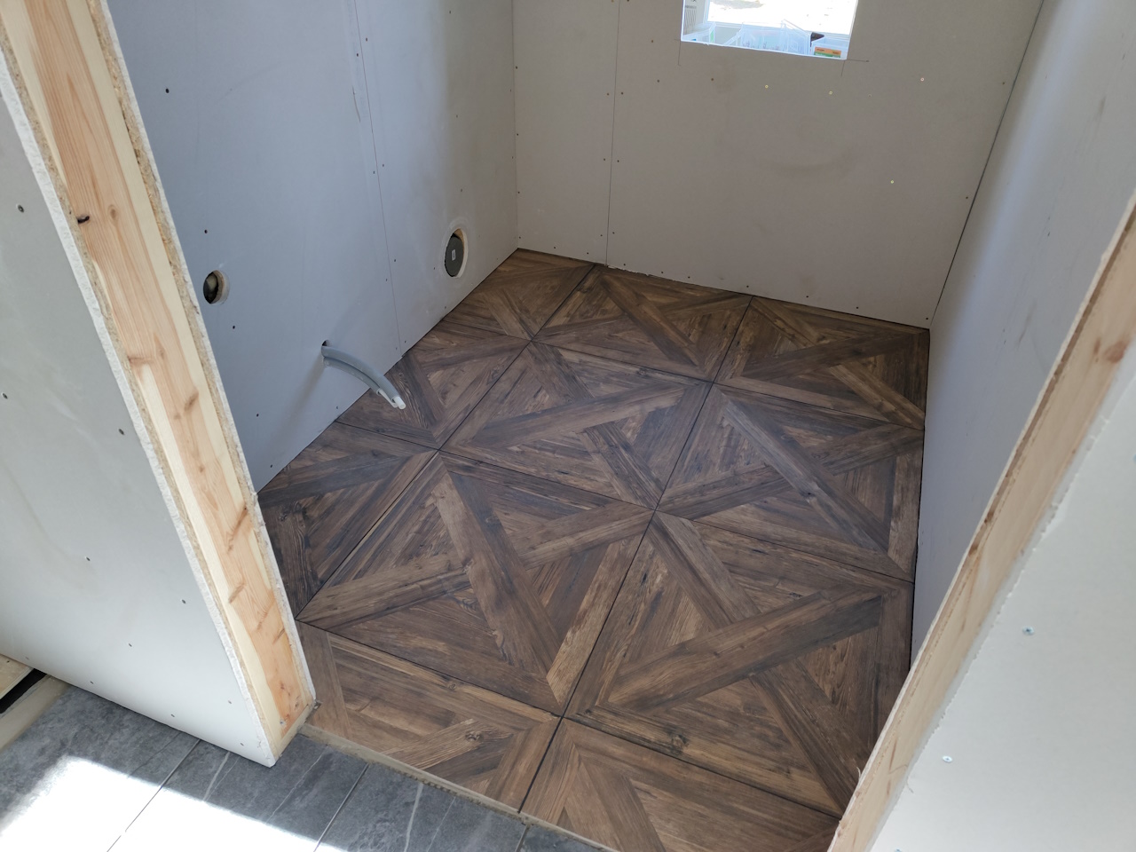
The house project is coming along nicely and we’ve put down the floors in the entry and wc-spaces. These are ceramic tiles which is super nice combined with the floor heating. So this is where most of the ”hobby-time” goes nowadays.
I’ve finished yet another bafang-ebike build. This time with the neighbours kid and he’s got a custom RR-battery too. Works great and he’s super happy with the bike!
We’ve yet again restarted the #EOD simchair project, this time making the frame from a sturdier and more easily joinable material..
Making a welded steel frame makes it easier to get all the angles and mounts where we want them.. and it makes for a super sturdy frame that won’t bend like the bolted aluminium one did. More on this project in future posts.
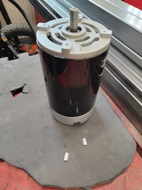
I tried to mill some wood with my manual mill too, which the 500w motor mounted on there didn’t like.. so it tripped the ground fault breaker and didn’t want to start again.. Had to order a replacement motor for it, this time an 800w motor. We’ll see if the electronics can keep up but from what I can see the mill was built to accomodate the bigger motor.
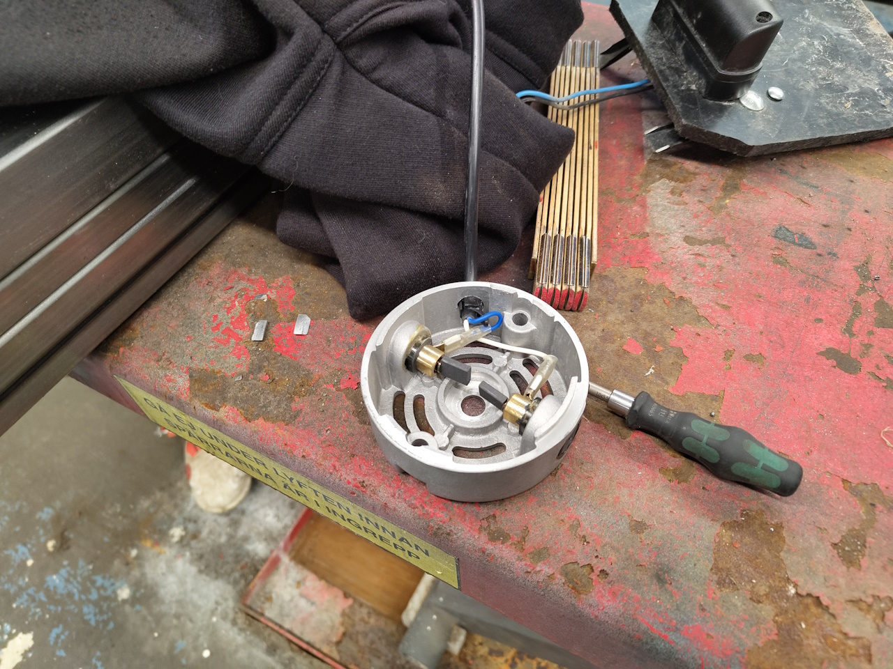
Unfortunately the new motor was broken when I got it.. as soon as I unpacked it two metal pieces fell out and the motor didn’t turn around. Easy fix using parts from the old motor, but quite annoying still.
So, for the future projects?
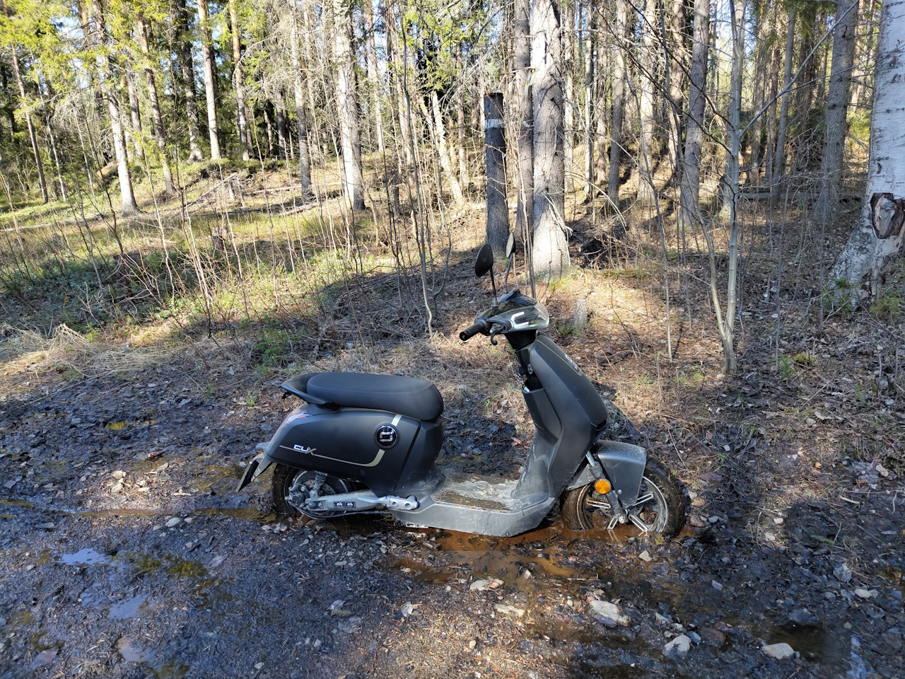
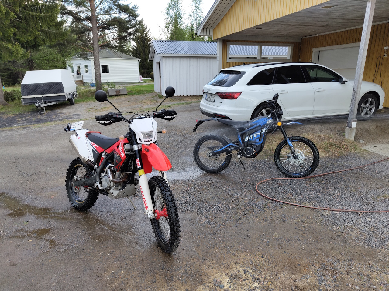
We got the kid a Talaria Sting for his 15:th birthday and I’ve been trying to go offroading on my moped too.. It’s not quite the right tool for the job though, so something had to be done about that..
.. so I went and got myself a 2012 Gasgas 250f with the intention of making it electric. It’s not running right at the moment, and it’s super noisy and while the plan was to run it as a petrol bike this summer and do the conversion come fall, maybe those plans’ll have to change..
I’m going to use the QS180 motor that I’ve got in the avant for the bike, as it’s peaking at 5kW in the avant and that’s pretty wasteful as it can do more than 32kw continuously. Got the controller and batteries and all, display and DCDC converters are on the way from china.
So, the first project will be replacing the QS motor in the Avant with the LightningRods XXL that I’ve got on the shelf. That’ll probably be what the next post here will be all about, before starting the NoGas conversion of the 250f.
Well, that’s all for now. Stay tuned for more project updates.
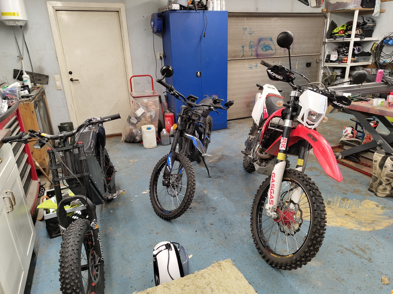
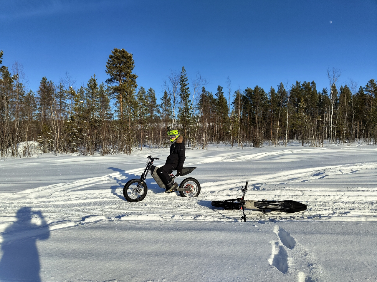
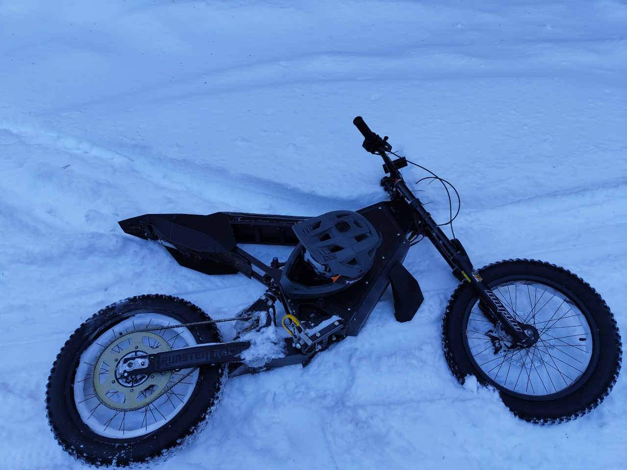
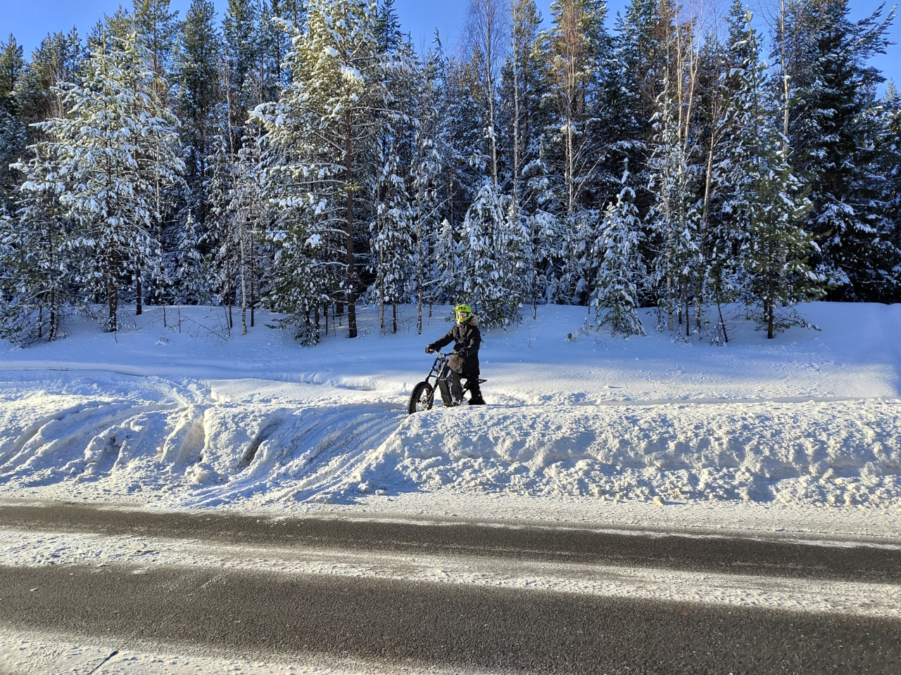
Today we finally got some sunshine and took a ride on our RunBikes on the snowmobile tracks.Since we’ve had super cold weather the last few weeks the snow hasn’t gotten hard, so the tracks are super soft and tricky to ride. For february the conditions are super though.We did a few minor (and some a bit more than minor) crashes but no injuries and apart from a lost rear fender the bikes stay together and run great. Unfortunately I got a crappy angle on my gopro camera so the video sucks, but I managed to get a few good clips from some of the crashes.. so when I get around to it I’ll post something here.
Super nice to start riding again, let’s hope for a great spring this year and loads of riding!