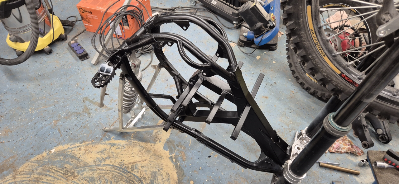
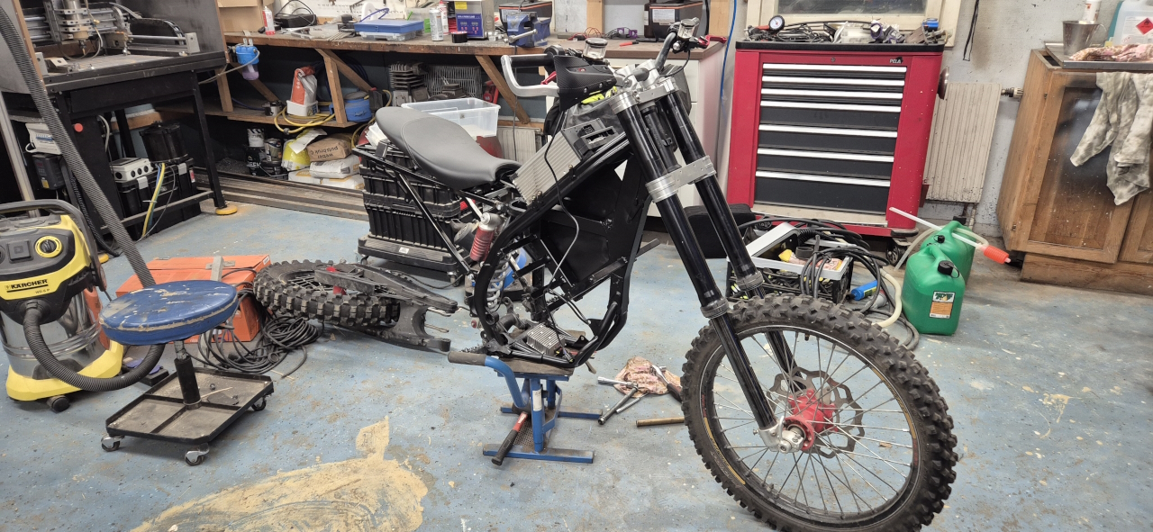
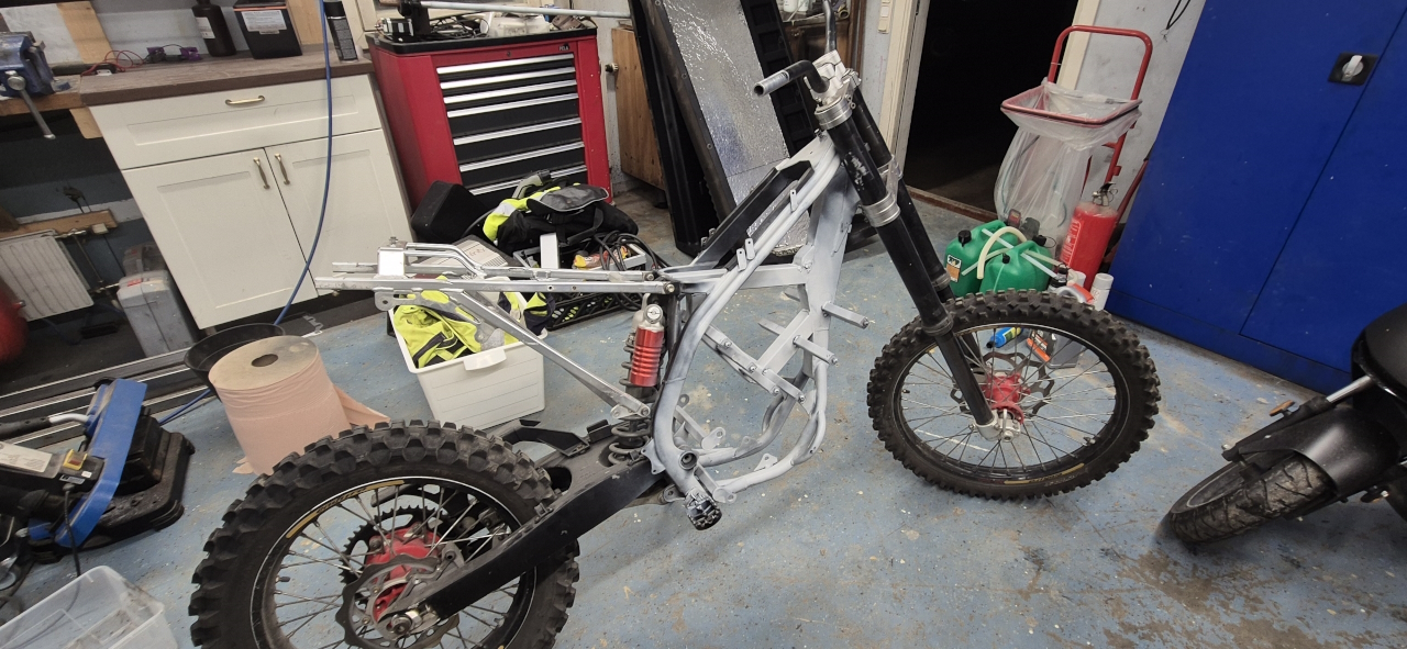
Since it’s started to gather some surface rust I decided to paint the bike frame even though I’ll need to repaint it later after welding stuff to it.
I did some kind of paint job on the subframe as well as it looks nicer when the entire frame is black.
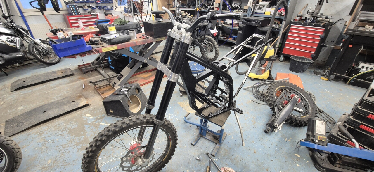
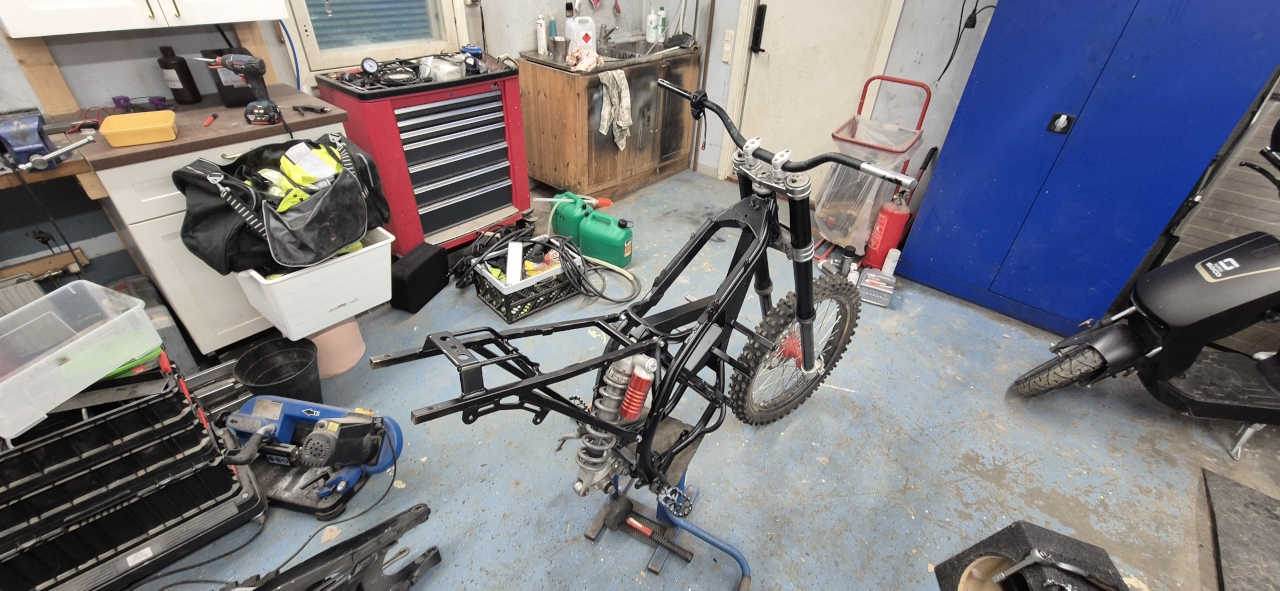
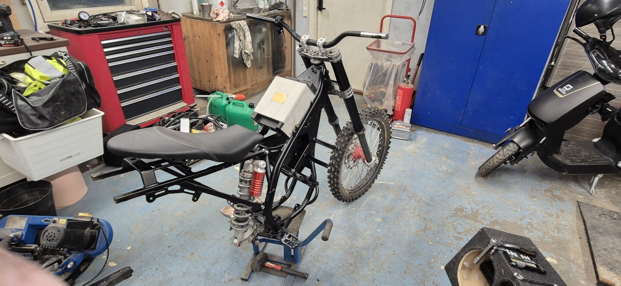
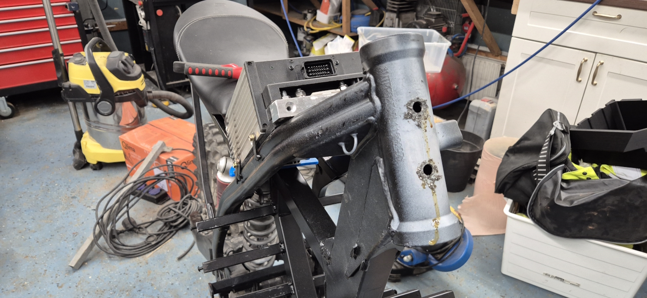
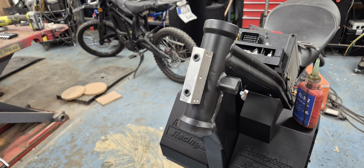
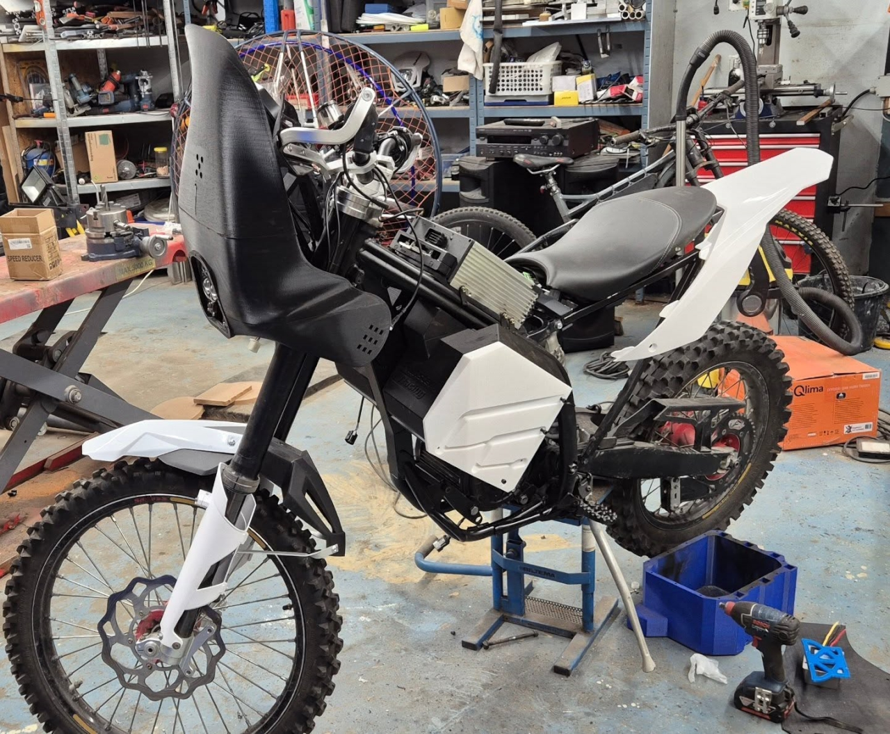
I installed the APK controller and put the seat on to get some hint of the placement of it all.
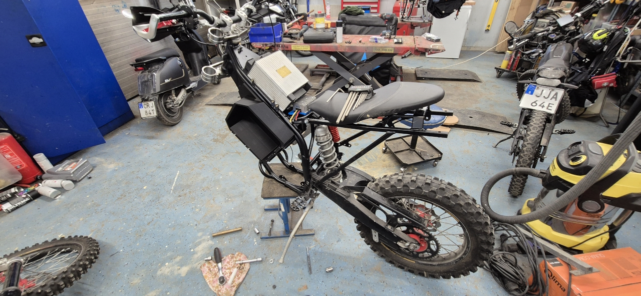
At about this time I figured I might just as well put a windscreen on the bike as it’s going to be wide and heavy like an offroad bike anyways.. so I did some cad, removed the front part of the bike and..
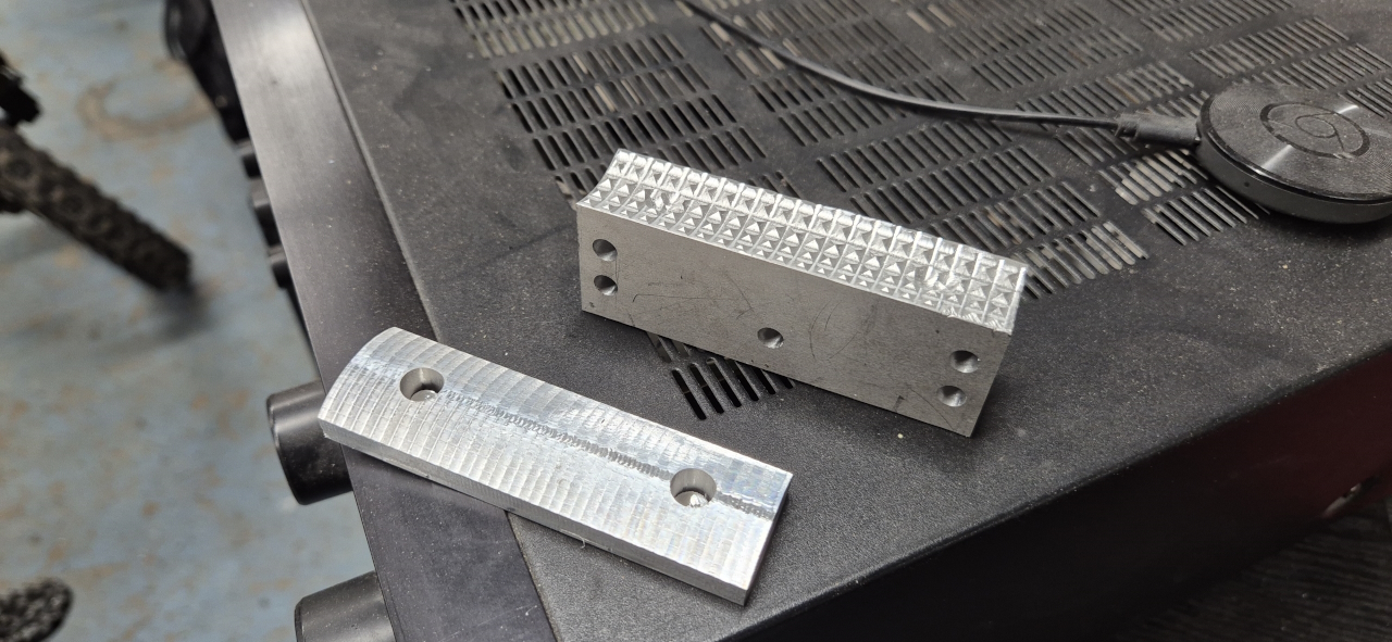
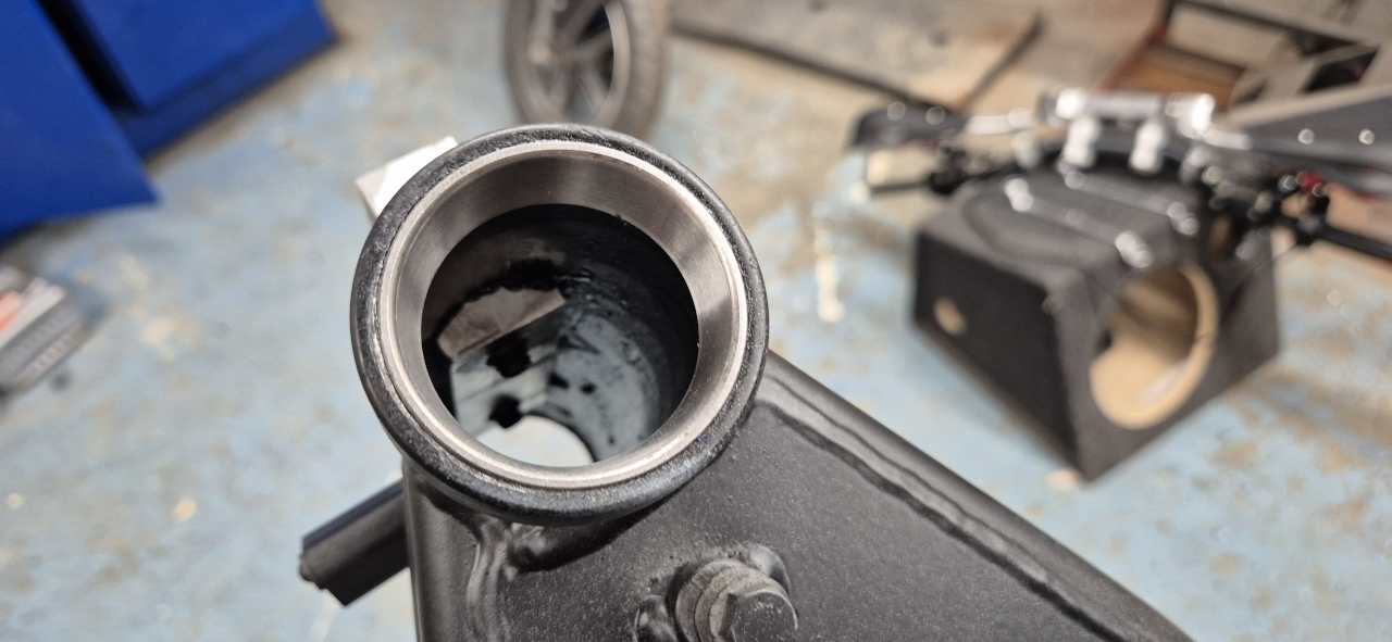
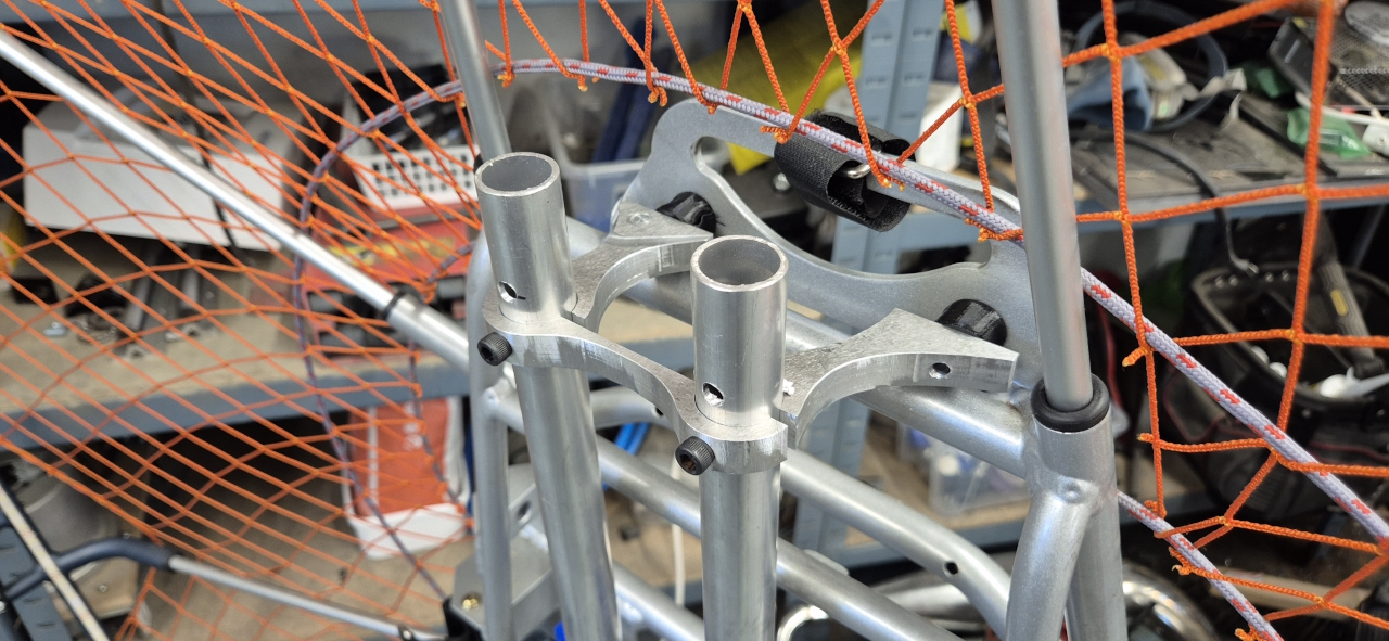
Drilled matching holes in the frame and put threaded inserts into the aluminium parts for them to last.
And after installation..
Making sure the bolts doesn’t interfere with the steering stem on the inside and we’re good to go.
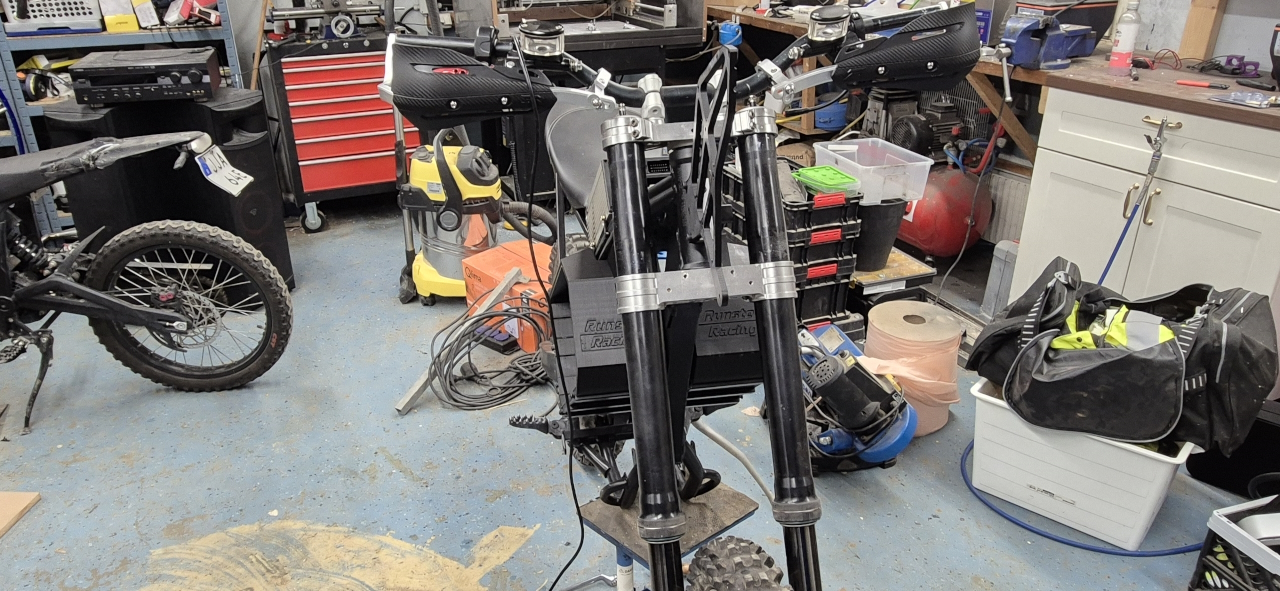
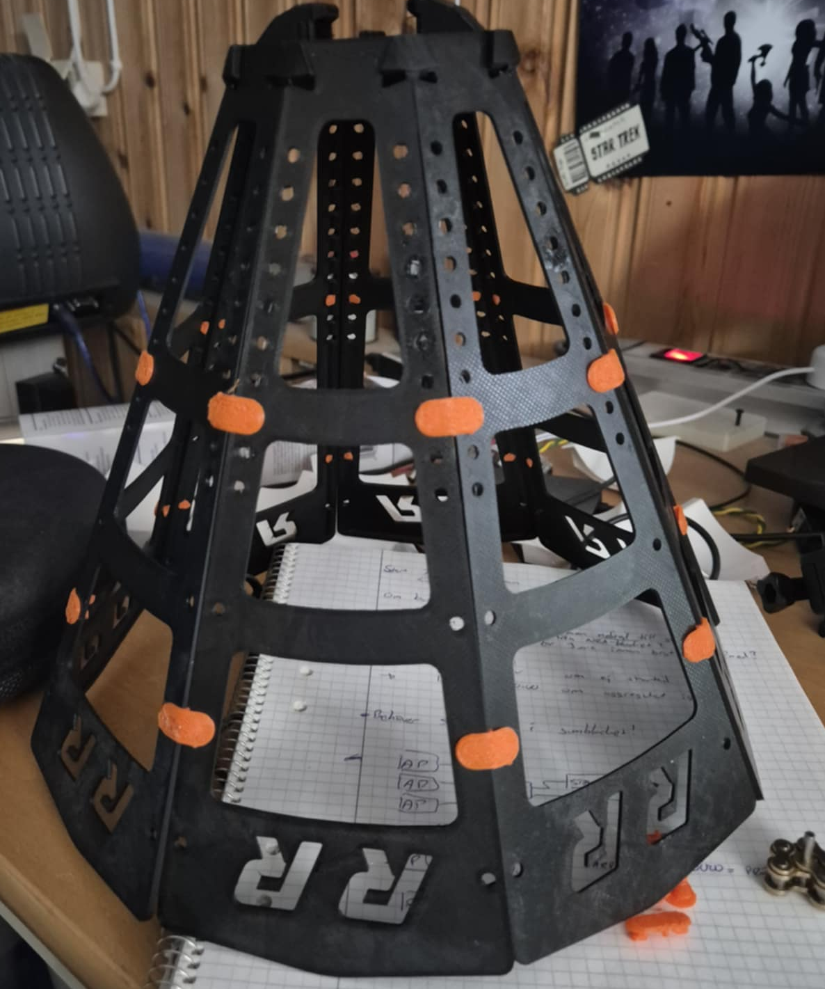
Started mocking about with some printed towers and realized it’d be fun to try to use a 100% 3D-printed tower and fairing.. so ..
I printed the base of the tower, added threaded inserts where needed and put the headlight and instrument cluster on there.
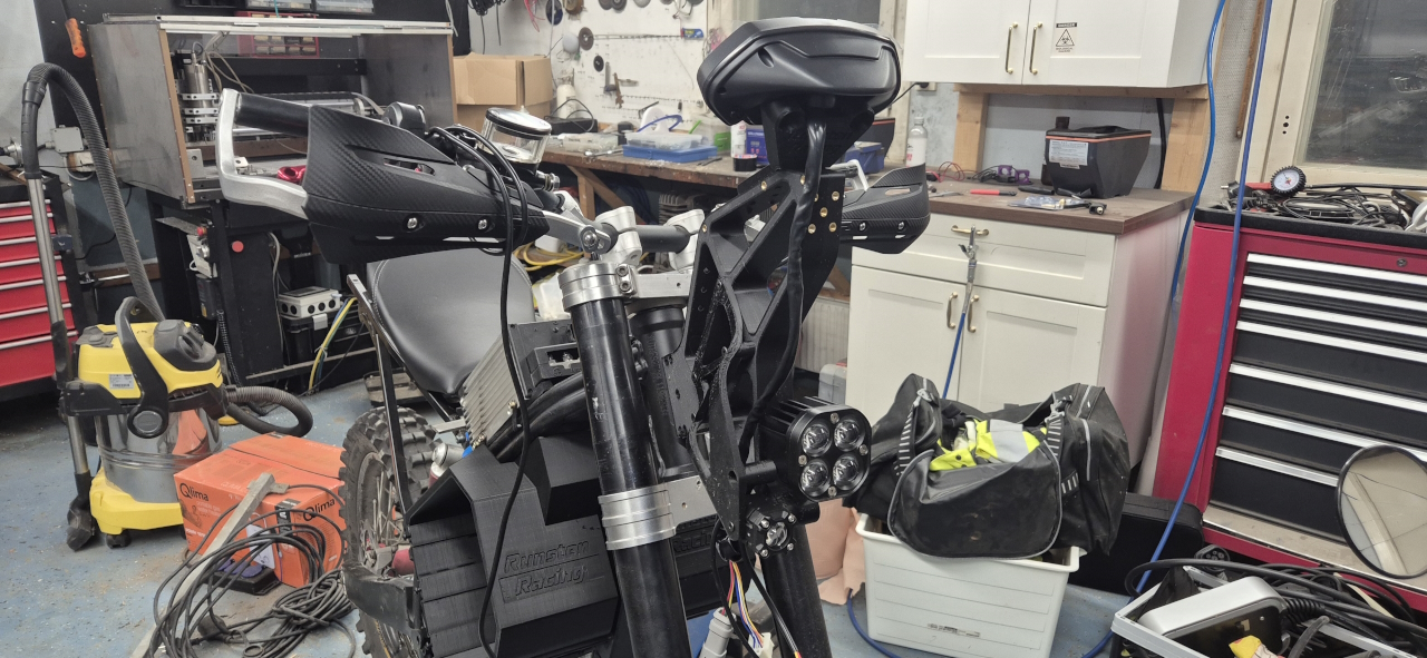
The next step was making a fairing.. and while it looks ok in CAD..
It felt a bit too thin in real life.. so, remaking the fairing once more..
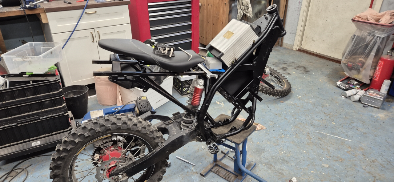
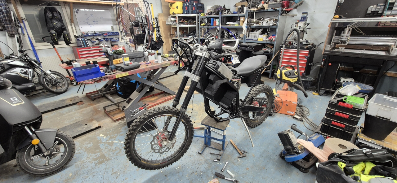
Not perfect, but it’ll do for now. Got a low front fender that I made a mount for and I’ve made custom brackets to secure the seat on the bike… The battery box covers will be white with some black carbon fiber inlays, just for the looks of it and some rigidity.
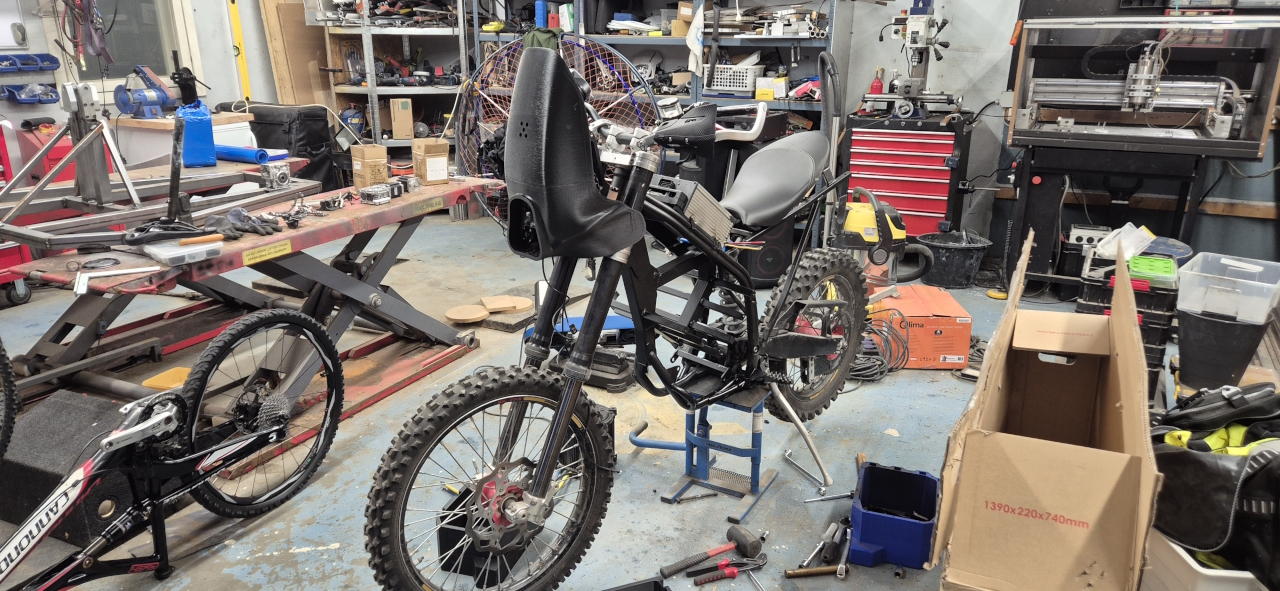
Now all I have to do is wiring, brakes, lights, chain, controller setup and some cover plates under the seat… then I think we’re good for a test drive.. Let’s see if we’re there before next update.. 🙂
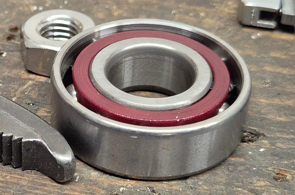
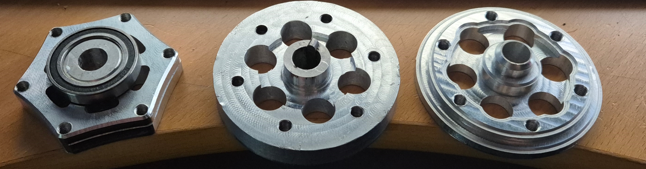
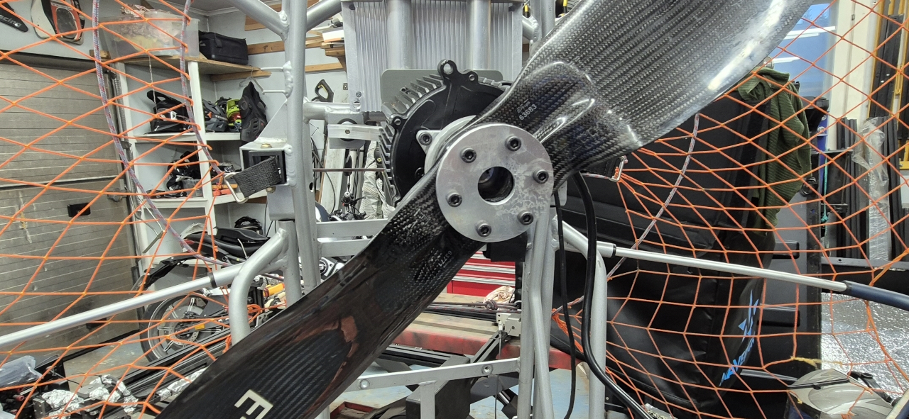
After last weeks trial run the squeeking sound of the bearing kind of hinted at the fact that my normal ball-bearings didn’t like axial forces.. and the propeller is mostly pushing axially into the bearing.. so, time for improvement and redesign..
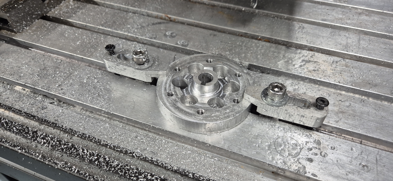
I found a couple of angular contact bearings and updated the CAD with the new dimensions. The parts I needed to modify was the support-bearing-mount and the propeller mount itself.
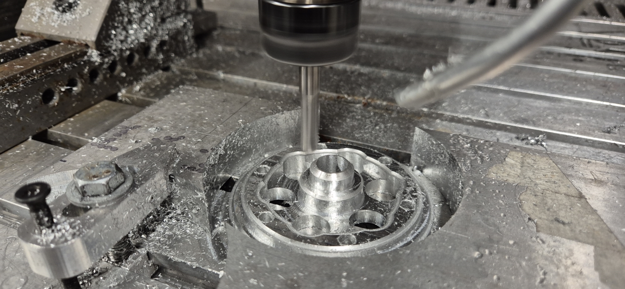
I had a little bit of problem getting the CAM to do what I wanted it to, but after some struggle it turned out great.
Since i broke the millbit I usually use for aluminium I had to replace it, and MAN was that old bit dull. Quality is superb after replacing it and the part turned out so good it’s a shame it’s going to hide behind the propeller so it wont be visible!
This is progression in the garage. Version 1,2 and 3 of the propeller mount. Version 3 is the lightest by far and less weight is good weight..
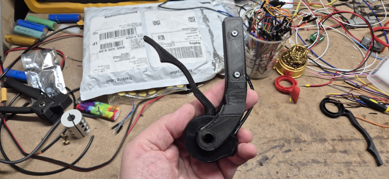
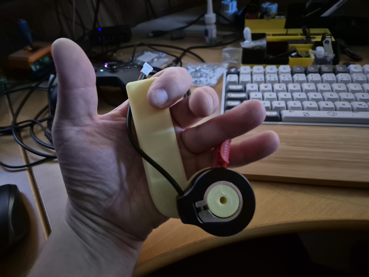
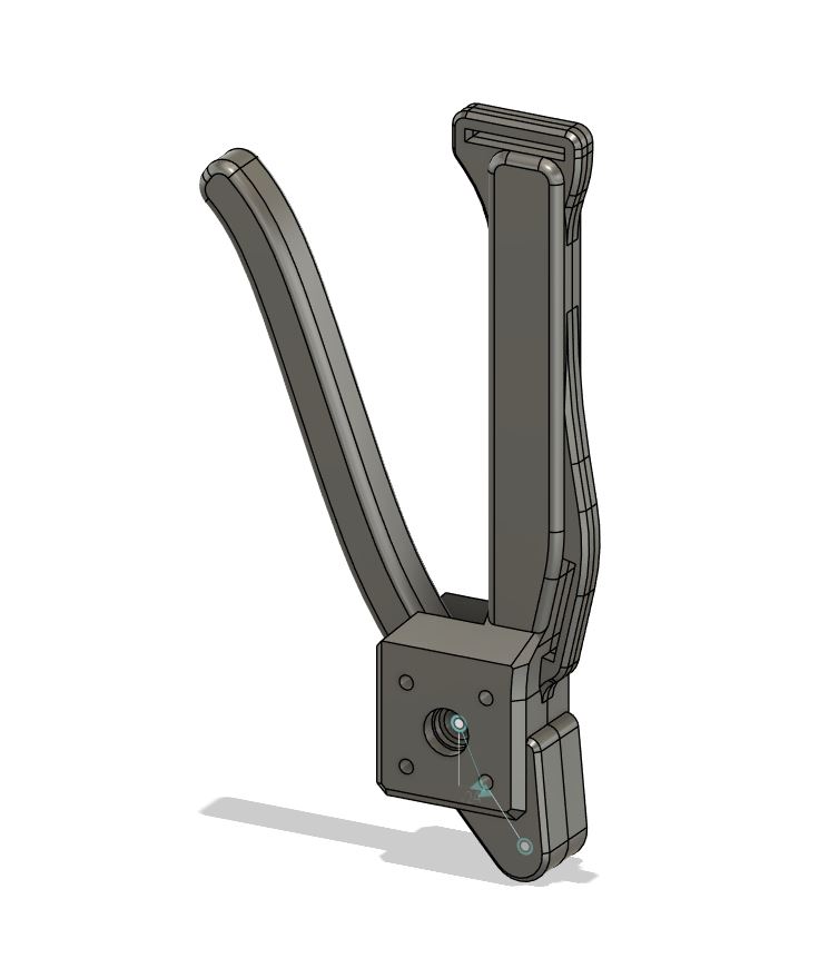
Since I’m doing a DIY project I wanted to make a throttle that I like. The ones I’ve seen online are far to bulky to fit with heated gloves in the winter and kind of annoying too. I started off with a regular e-bike hall-sensor trottle, designed a new lever for it and built a handle.
It’s still a work in progress. Going to fit a couple of buttons and the display on there too.
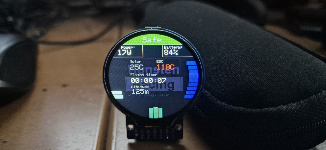
The display is a standard 240×240 display from Amazon. I’m using an ESP32 to run all the functions like arming, cruise control, battery state monitoring and so on. The plan is to implement functions for remote activation of beacons and maybe different power levels. That’s on the todo-list anyways.
Since I’m using an ESP32 it will be possible to implement wireless control. Just adding a battery to the throttle could make it so the cable between the throttle and ESC isn’t needed. I’ve considered that option but don’t know the reliability of the wireless connection in the environment we’ll have. Starting off with a wired controller, wireless is a later option after loads of connectivity testing.
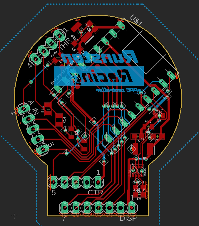
For those of you that are into PCB design, here’s a screenshot of the control-board before pouring the ground plane. I’ve added inputs for 2 buttons, made options for controlling the FarDriver directly via the throttle or through the processor. I also added a barometric altimeter to the PBC to be able to get current AGL and temperature.
Well, that’s all for now..
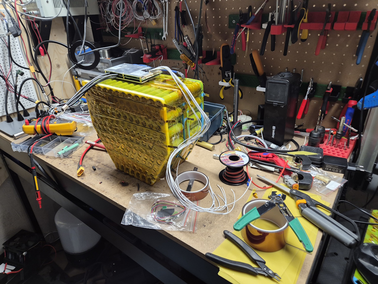
I’ve also finished the battery mounts on the NoGas project, and primed it for paint.
We needed a shoe rack but all my 25mm tubes were rusty, so I built something like a lathe to remove the rust from it.
And I’ve bought a snow blower to fit to the Avant.. currently designing electric control for the turret on it.. but more on that in another post.
I of course had to build an electric one for myself. Petrol is good and all but messing with re-fueling and mixing oil and gas, and just going to the gas station is quite tedious… so here we go.
I got ahold of an old broken paramotor from a friend and started 3D-printing prototype mounts to fit. I wanted a general solution that could easily be fitted to a range of paramotor frames so I based it all on two 25mm aluminium tubes.
3D-printing parts is the perfect way to test fit before doing a more cumbersome and costly aluminium part.
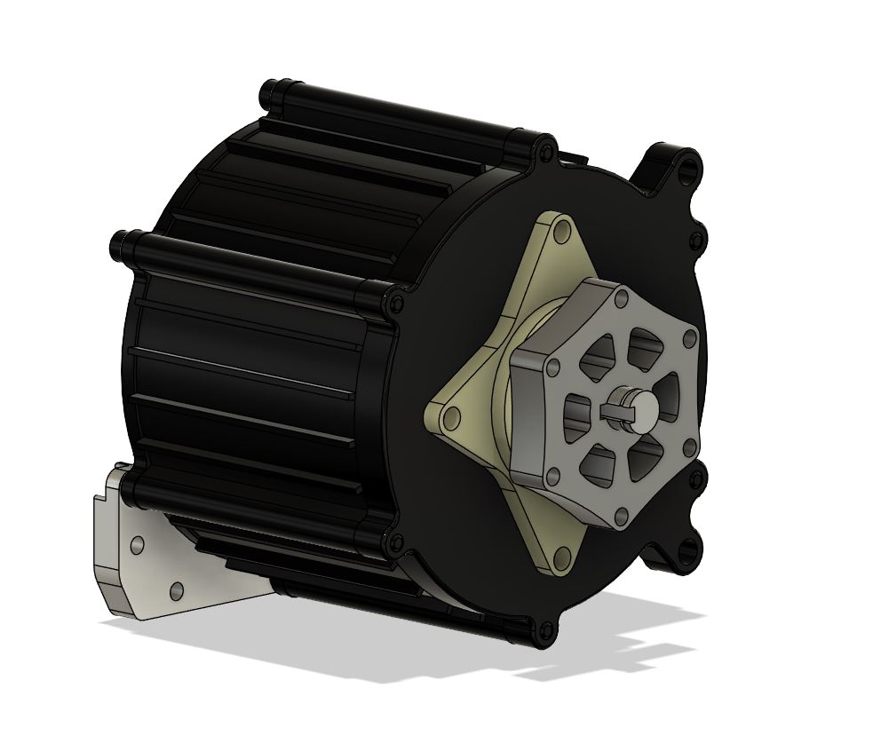
I am basing this entire project around the XL motor from LightningRods as I had a couple of those from another project. For those of you who aren’t familiar with the LightningRods range of motors you can find more info on the LightingRods website:
To control the motor I need to make a paramotor-style throttle grip. Have been thinking about making it wireless but that’ll get to be version 2. First we’ll have to get this one up in the air, så keeping it simple at the moment.
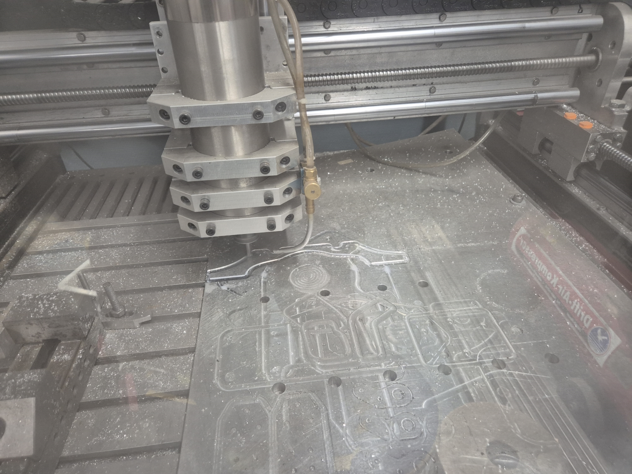
The mill got busy making parts when the test-fitting was done. Man this thing is practical.
Aluminium on aluminium just looks so dang nice. =)
I did need one part that was hard to make on my mill. Even if I started making a larger vise to hold the part on the mill I just tried to order a couple instead. Ordering was not that expensive and the quality is outstanding! If I’m building more of these I’m going to order all parts online instead of wasting hours on the CNC mill at home.
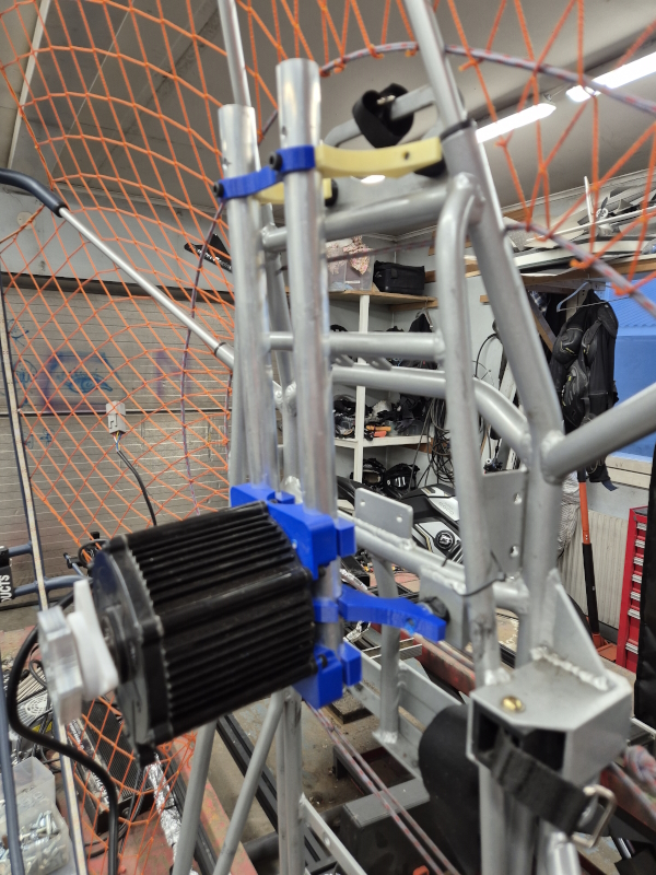
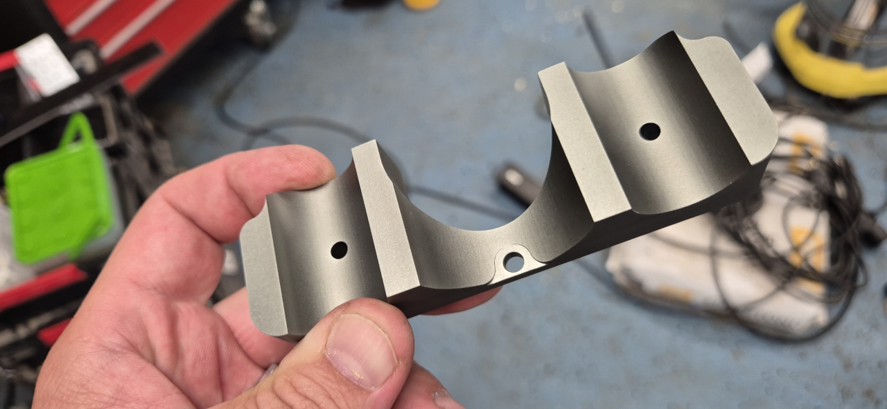
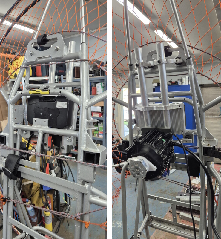
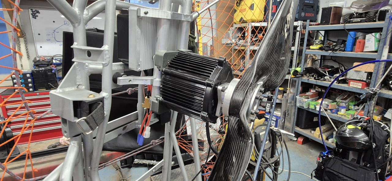
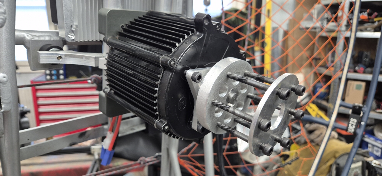
Made a mount for the FarDriver that fit on the tubes and here everything is milled except for the support bearing holder and the proper propeller mount.
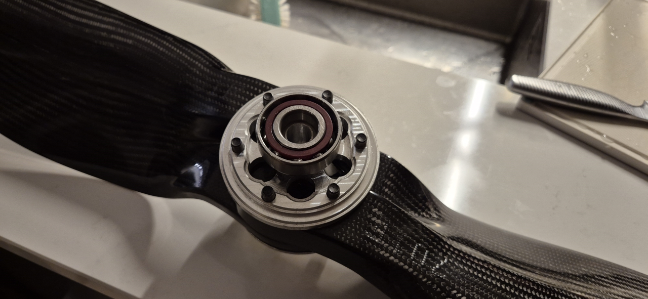
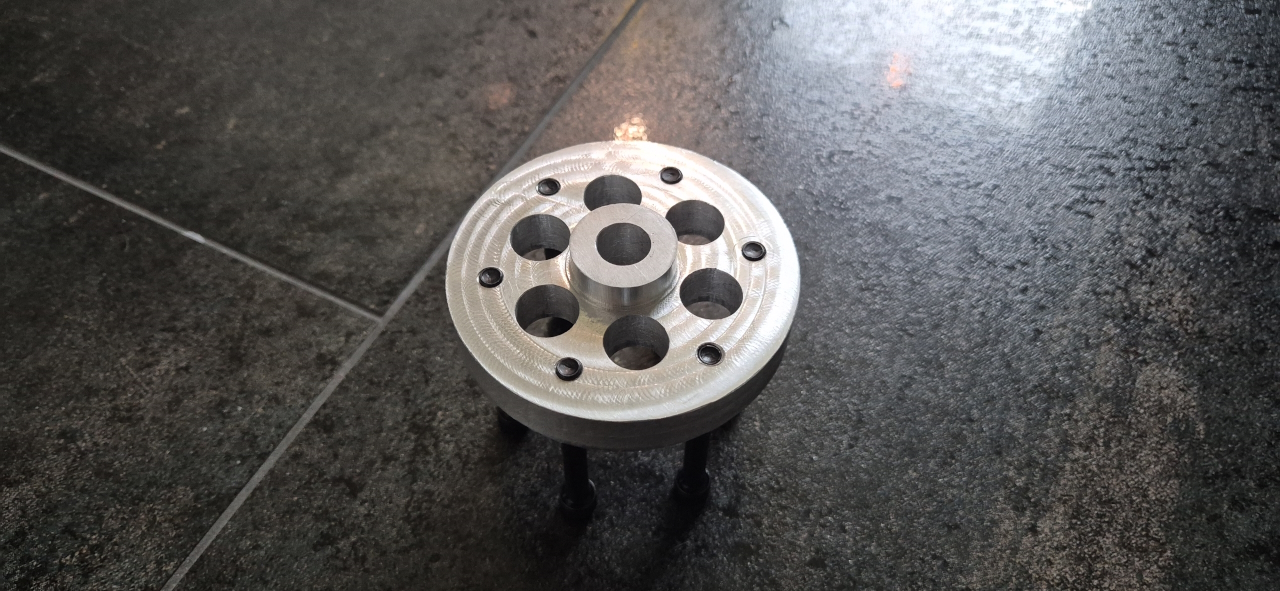
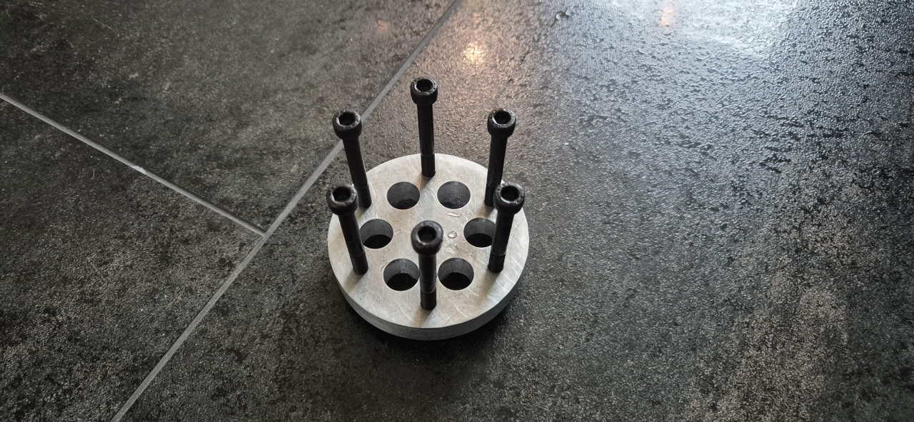
Made a propeller mount for a propeller fitting a Vitorazzi Moster 185, since that’s the propellers I’ve got. On the back side a bearing is mounted and the corresponding part that bolts on to the motor gives support to the propeller. That way the internal bearings in the motor won’t see so much axial load. I did mount a regular ball bearing at first but I need to replace that with a preloaded axial bearing to unload the motor bearings better.
Milled a counter plate for the propeller and test fit it. The motor has plenty of torque and when shorting the phases there’s plenty of resistance in the propeller.
Here you can see the way the propeller support bearing and the propeller is mounted. I started out with quite a slim bearing but had to replace that with a proper ball bearing that could take more load. It’s supposed to be able to take 100kg axially but I don’t really trust those numbers.
In order for the new bearing to fit I had to do some modifications on the mill.
Everything feels sturdy enough and should give proper support for the forces applied when flying.
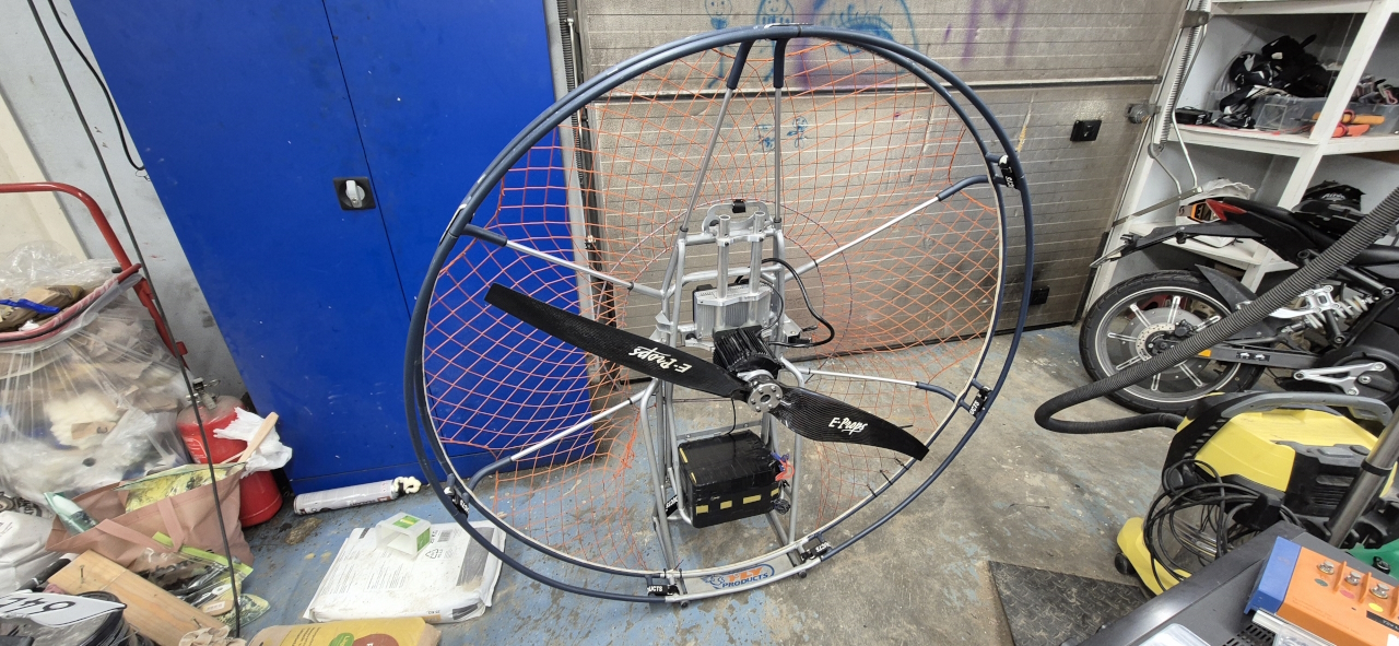
Using a battery from one of my bike builds to test this thing out. 20s10p, 30Ah good for 300A+. Total weight of the frame with controller and motor is around 12-14kg. The battery pack weighs as much and I’m guessing with the harness we’re getting closer to 30kg with one battery. I’ve got one more to connect in paralell but we’ll start off with one for testing.
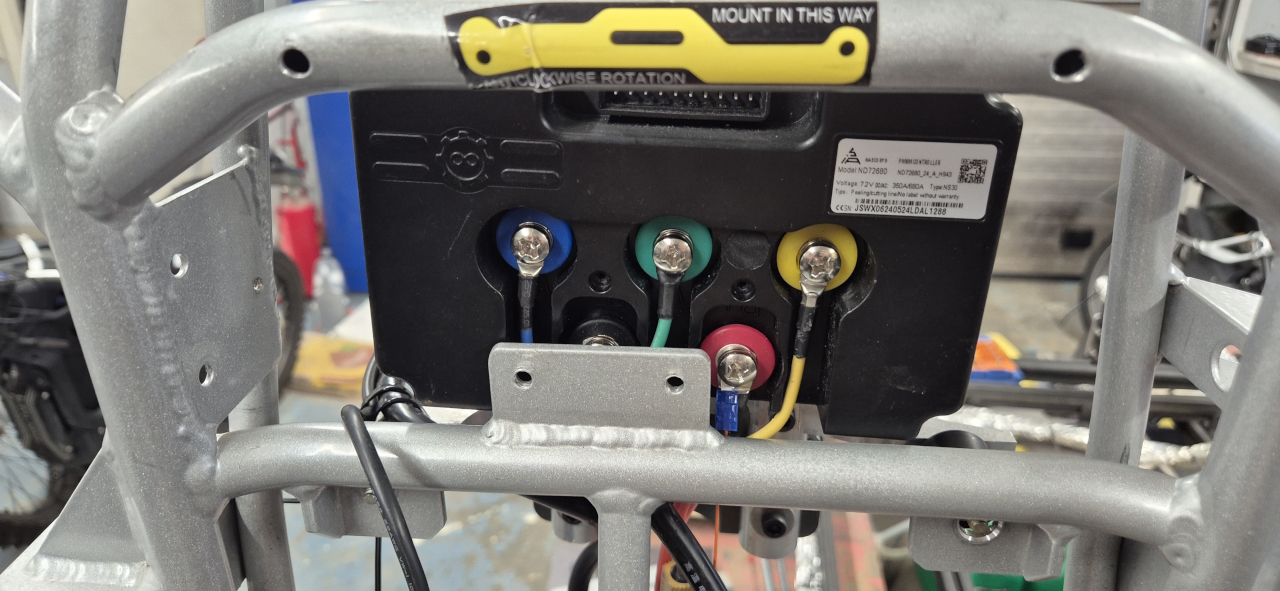
Wiring in the FarDriver couldn’t be simpler.
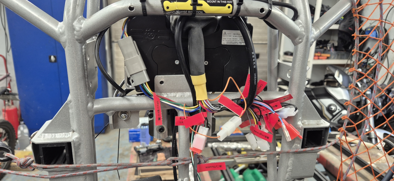
Next thing I’m doing tonight is cleaning up the wiring harness. There are loads of leads that I won’t need using the controller for flying.
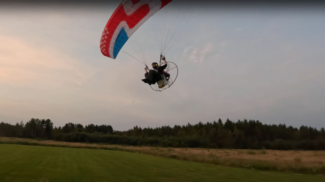
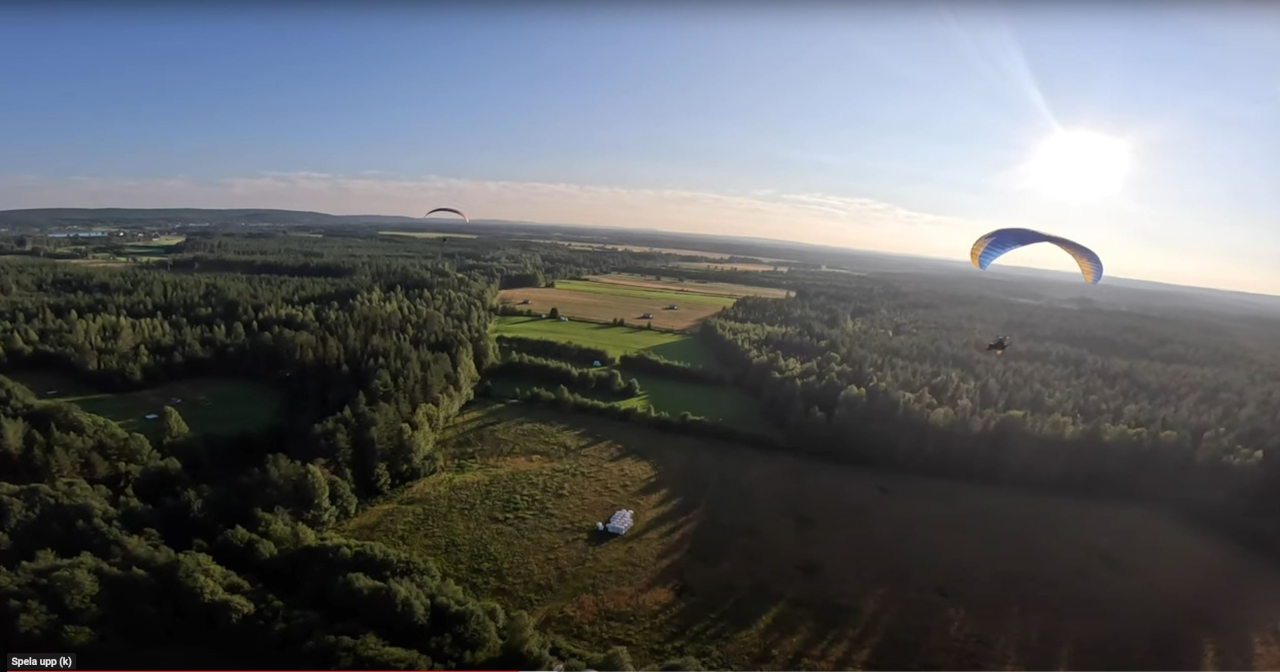
Just a nice picture from my first flight ever last summer. Got quite hooked on flying after that.
The first test run of the XL-ePPG went great. Got around 2900RPM on a prop that’s good for 3000.. Nothing got warm and the motor revs out all the way. I probably could tweak the controller to use field weakening to get more speed but we’ll keep it like this for the time being. The battery sat at 6% charge when I started testing too, so the BMS limited the output.. it’ll be interesting to see what this can do under a glider..
I’m sorry for the lack of updates this summer. We’ve been doing the final touches on the house project and I’ve been trying to get as many hours in the sky as possible for relaxation.
Autumn is here so there’ll be time for more indoors-focused projects now and the ePPG project will be ready for testing shortly. The GasGas conversion has been at a standstill but I’m working up the energy to finish that one too. 🙂
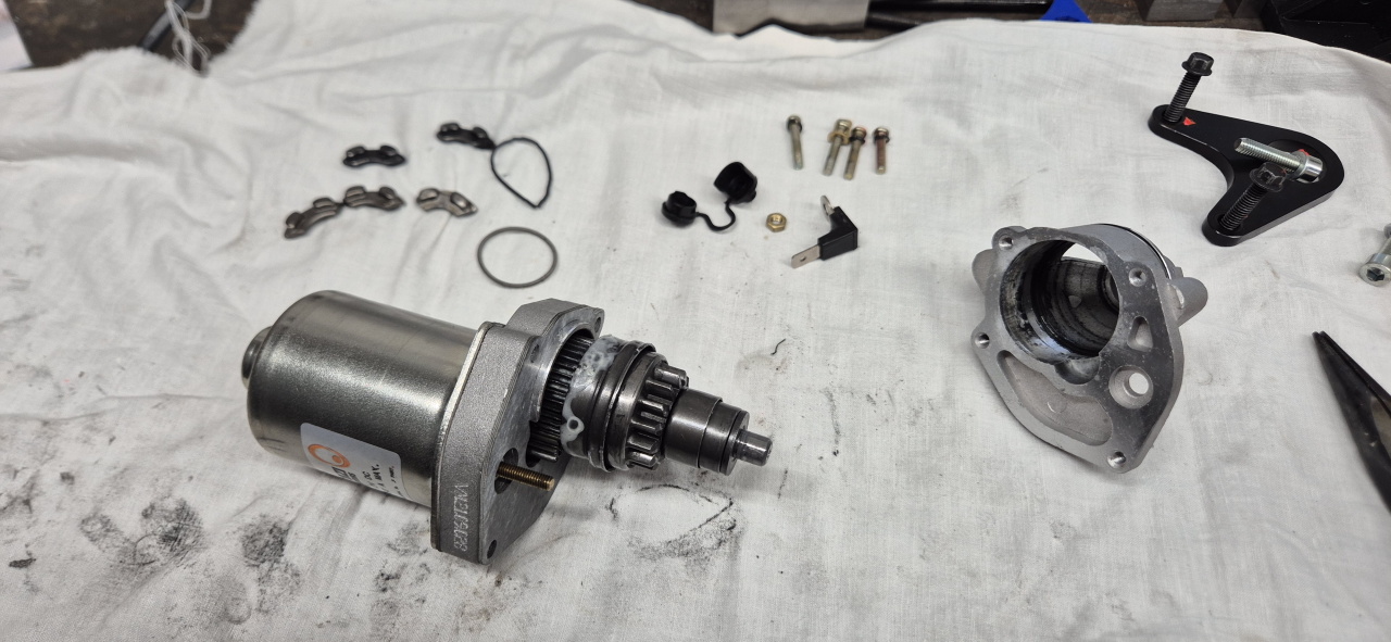
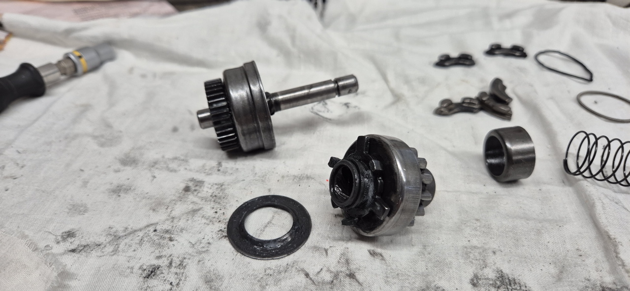
So, while adjusting the carburetor on my paramotor due to the heat-wave we’re experiencing I got a super loud noise and instantly killed the motor. When carefully pulling the pull starter I found that the sprocket of the electric starter didn’t retract all the way and stayed partially in contact with the starter gear on the motor which.. isn’t great.
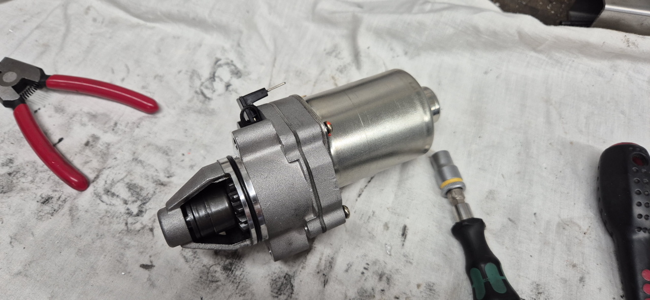
I pulled the electric starter motor out to have a look and it didn’t look right..
When connecting 12V to the inputs the sprocket was thrown out but instantly retracted half way. When disconnecting the power it didn’t fully retract so something made it stick.
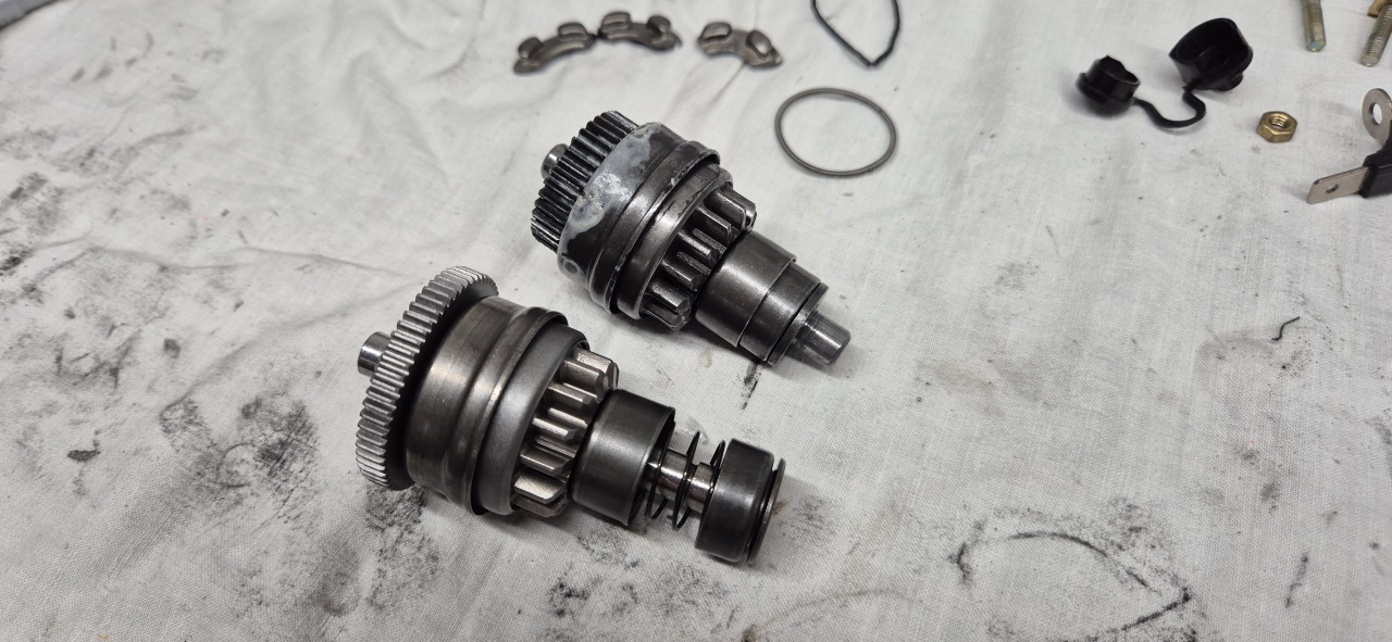
The starter motor is fairly simple to disassemble:
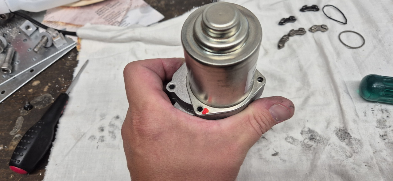
Four screws holding the motor casing and gearbox together and
the brass nut connecting the positive pole to the motor. After removing those the gearbox slides apart easilly.
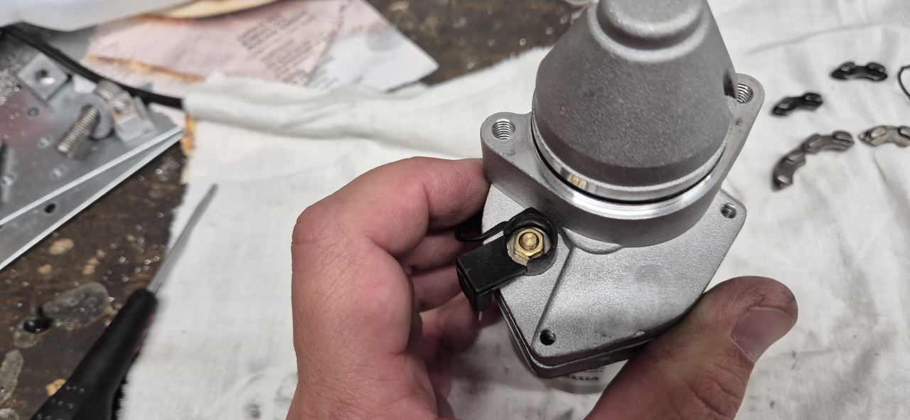
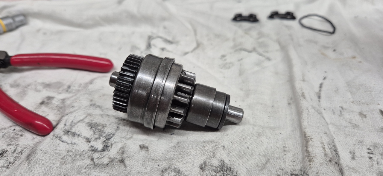
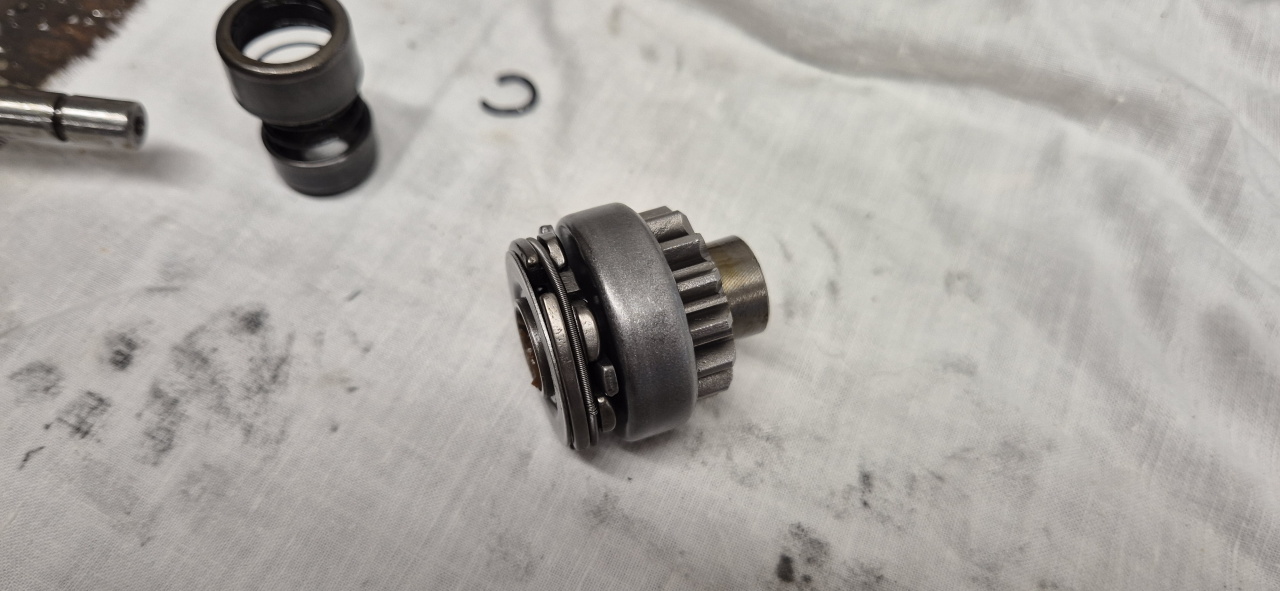
The problem when the sprocket doesn’t retract is in the bendix gear that’s responsible for keeping the sprocket in contact with the starter gear as long as the electric starter is engaged. Had a look at the bendix gear and there was a wierdly shaped rentention spring partly protruding and some loose parts inside.
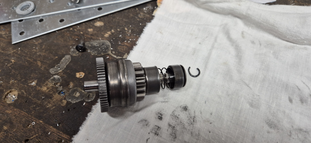
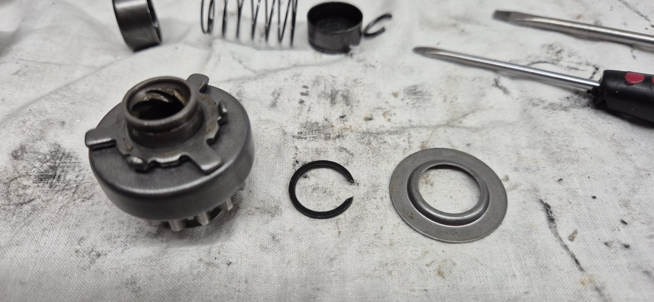
To disassemble the bendix gear you need to remove a retaining clip that can be accessed by compressing the internal spring by pushing the rightmost cup downwards.
After removing the retaining clip the entire spring compartment slides off the shaft.
With the spring compartment out of the way the sprocket housing with the weights should rotate right off. Mine didn’t due to minor damages on the shaft so I had to convince it using a puller.
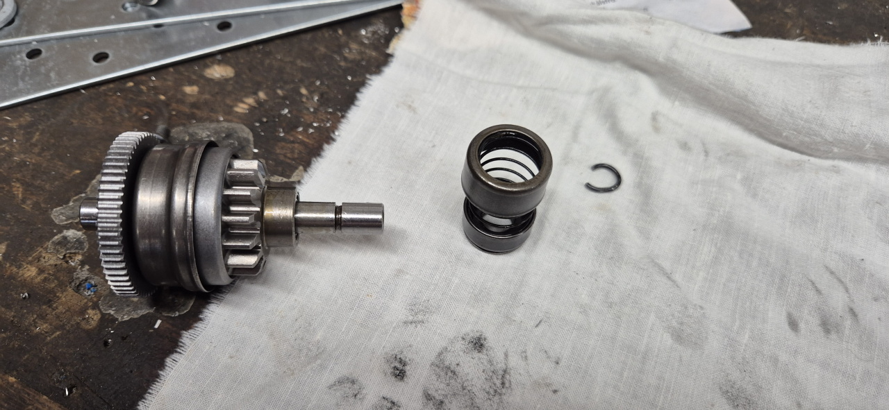
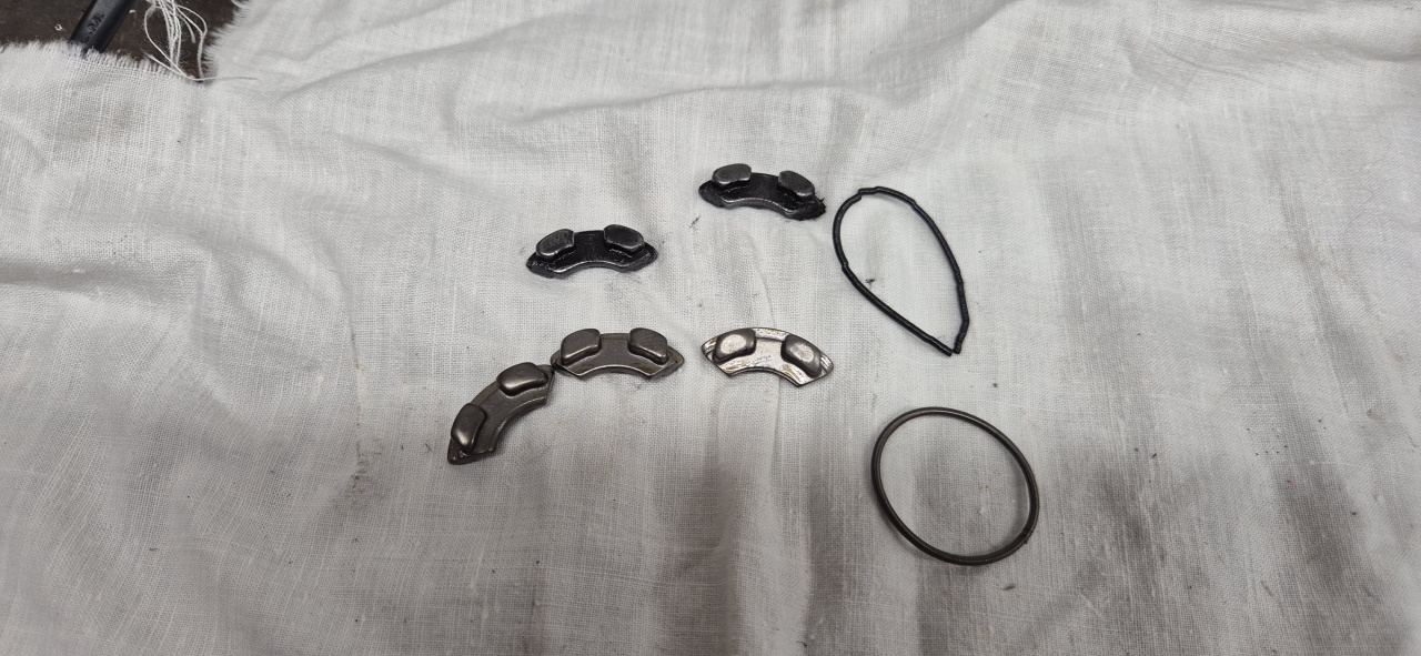
Taking it all apart I saw that the weights that’s supposed to lock the sprocket in the extended position had come loose and one was missing. It must have shattered to be able to escape the housing and in doing so doing some damage to the other components like the retaining spring and bottom containing plate.
At this moment I knew I needed a new starter or at least a new bendix gear. The gear was 66 pounds and 85 pounds shipping at the cheapest place I found it, and the starter is much more expensive than that. Since I’m allergic to shipping costs being higher than the price of the actual product I started looking at options.
First I thought I’d just make a copy of the weights in CAD and make one on the CNC mill, but that’s a lot of work as it is quite a complex part.. Then I started looking online for bendix gears.
It seems the Moster185 starter is similar to the starter used in many KTM bikes and loads of moped motors. I found a place in Sweden selling bendix gears for mopeds that looked similar to the Moster gear and at $19 with shipping I gave it a try.
The moped bendix gear is mostly identical to the Moster one except it’s got a different reduction gear at the leftmost end – and rotates the wrong way. It does however contain all the parts I was missing..
I put the replacement parts into the Moster gear, re-assembled the starter, installed it on the paramotor and it works like new!
I’m certain there are moped bendix gears with the right reduction that goes the right way and thus are identical with the moster gear but I did just order the first and cheapest one I found.
Note: I did try running the starter with 2 and none of the weights installed but it then disengages the gear on the motor as soon as the motor hits TDC, so all three weights are needed for the starter to work properly.
I’ve been riding the Cux for a bunch of years now and been really happy with it. The only downside I’ve seen is the range of the original 30Ah battery. Going carefully I could get 70km range on a good day but when exploring the surrounding area I constantly had to keep track of the state of charge to be sure to make it back.
So, what’s the solution to that? Of course – a bigger battery! 🙂
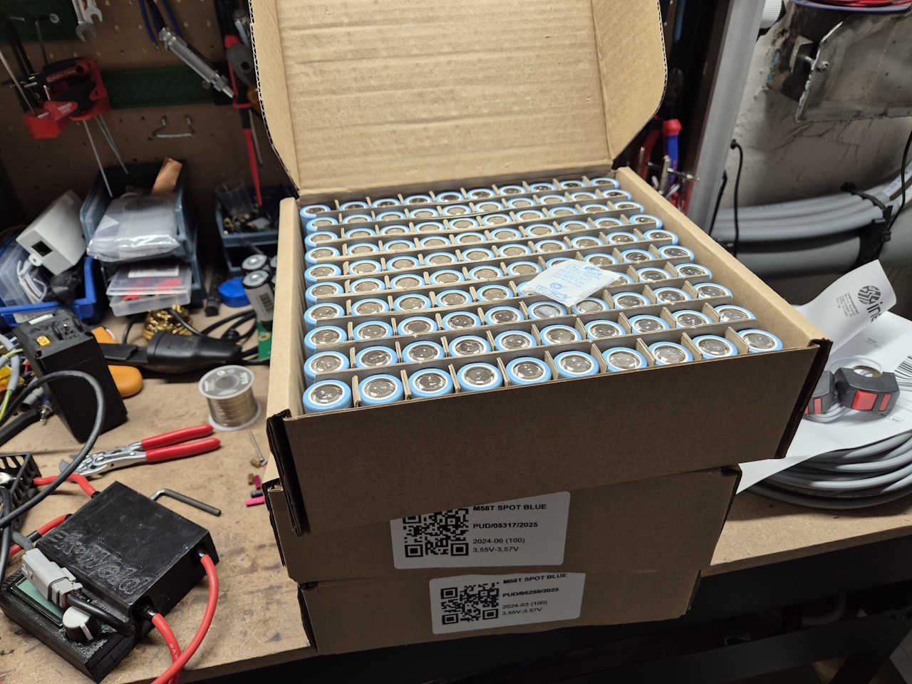
I removed the small storage compartment under the seat and made a prototype design. After test fitting and some redesign I figured I could fit a 17s17p pack of 21700 cells, so I ordered a bunch of LG cells with 5800mAh capacity. That set me back around $600, so not too bad.
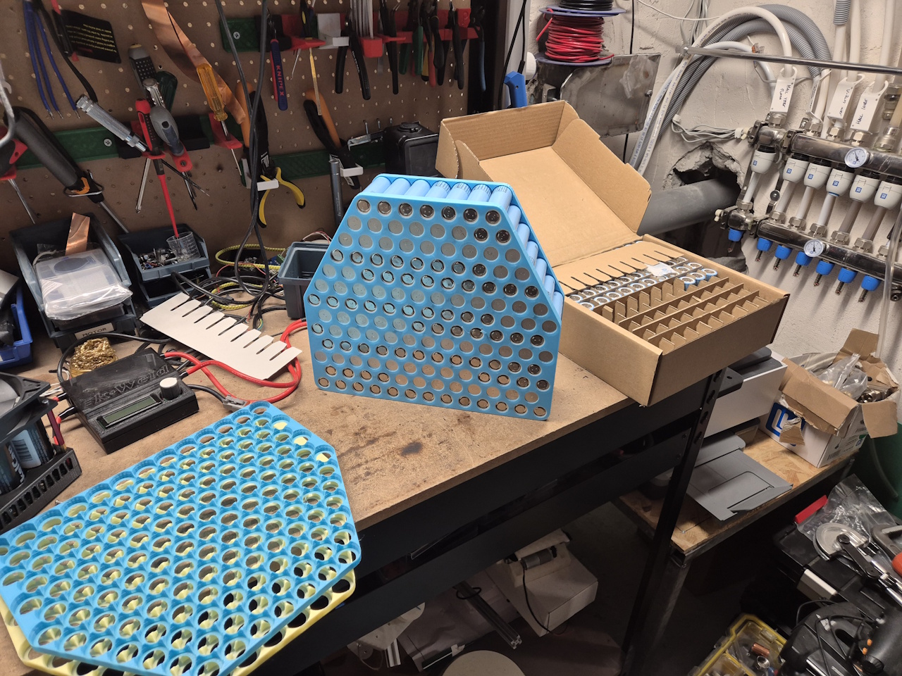
As usual I printed cell frames and figured out the cell configuration for the pack. The tricky part here is that 17s is not an even number, and I’ve got 2 sides – which is.. so I had to split one cell at the joint.
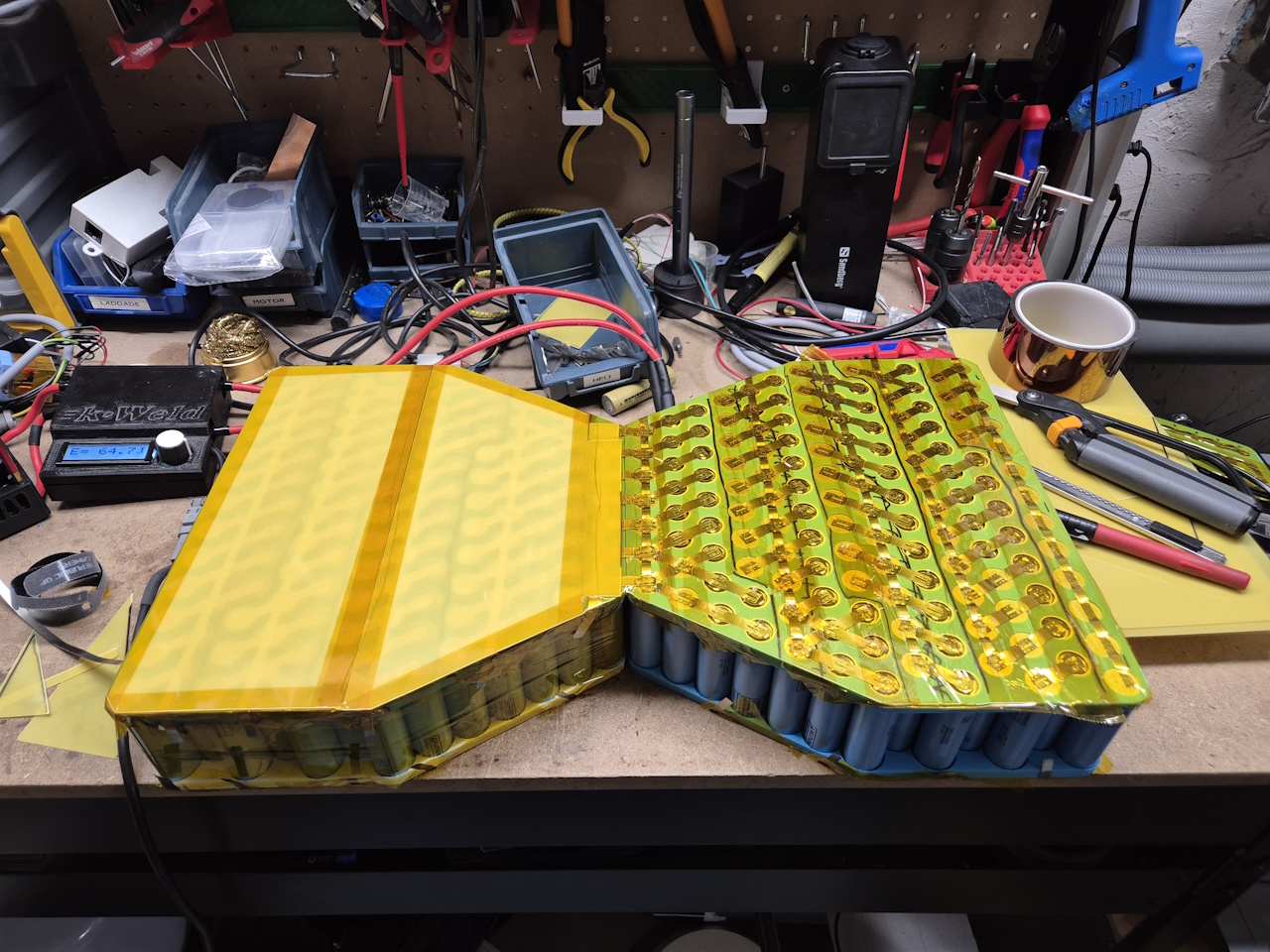
Since this battery will peak around 60A I didn’t use a copper sandwich but put down just enough nickel to handle it all. 17p gives a lot of connections anyways. Glass fiber insulation and time to fold the pack together.
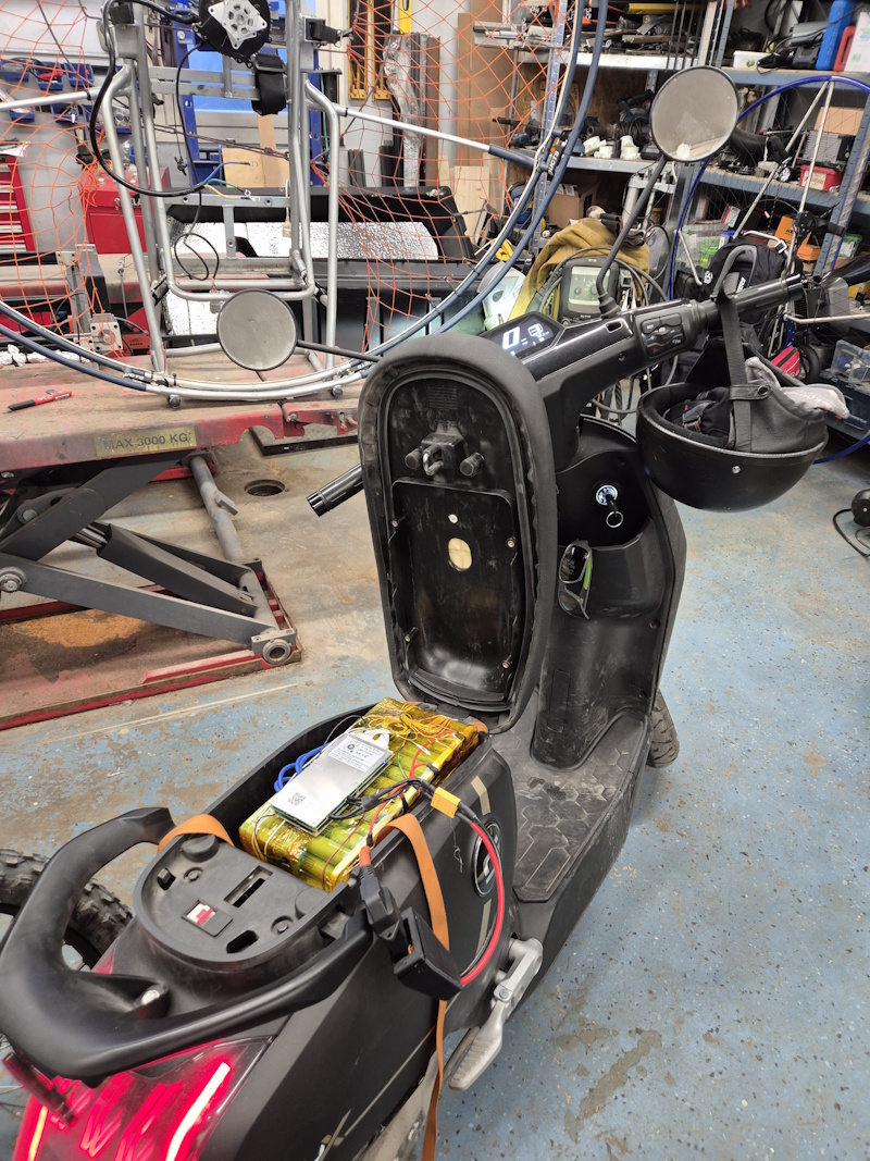
I’m using a 300A ANT BMS, since I had that at home. It’s a load of overkill but it works. I used a chinese communications module to talk SuperSoco-lingo to get the state of charge to show on the display and printed a case for the pack. It did turn out that the case didn’t fit, so I had to wrap the pack like it was and install it in the moped.
After a test fit and a wrap the battery charged fine with the original charger. The BMS however does not limit the charge to 4.1V like the original soco BMS but charges the pack to 4.2V. The result is that I now can ride 20km with the battery showing 100% charge. 🙂
So, the result then? On a full charge, at full throttle, going up hills and on gravel roads, I easilly get 160km range. Going a bit more carfully I get more than 180km and I don’t think 200km would be impossible with some gentleness on the throttle. Riding for 5+ hours is a bit much though but now I only charge the battery every 2-3 days. Huge success!
So it’s time to finish the house renovation that’s been going on for the past 15 years or so. We’ve totally rebuilt the entire house, from basement to upper floor with tearing out all the inner walls, doing new insulation, under floor heating and a three floor 50sqm extension to the house. So it’s been a project.
The last bit of renovation was to tear out the old kitchen and build a new livingroom. Unfortunately it turned out that the carpenter who did the old extension to the house took all the shortcuts possible, so we had to tear it all down and build a proper extension.. Now, 2 years later, we have a proper extension with good drainage and a concrete slab for foundation, and we’re starting to finish the project.
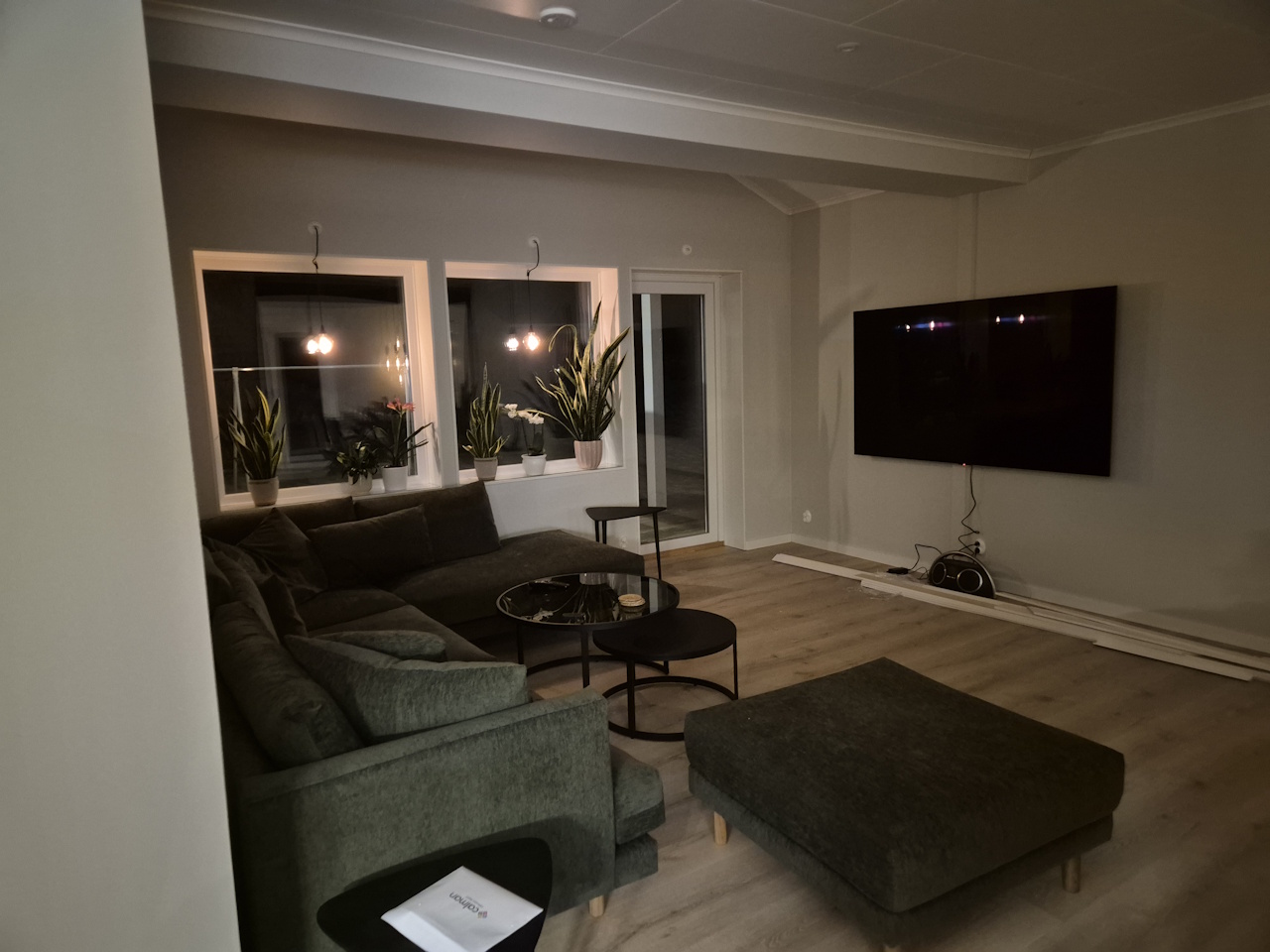
The livingroom turned out real nice, and the entire lower floor is without walls. There’s a fireplace in the middle of the floor, the kitchen is behind the camera on this photo and the dining area to the right. We’ve got huge decks on the front and back of the house which is awesome in the summer.
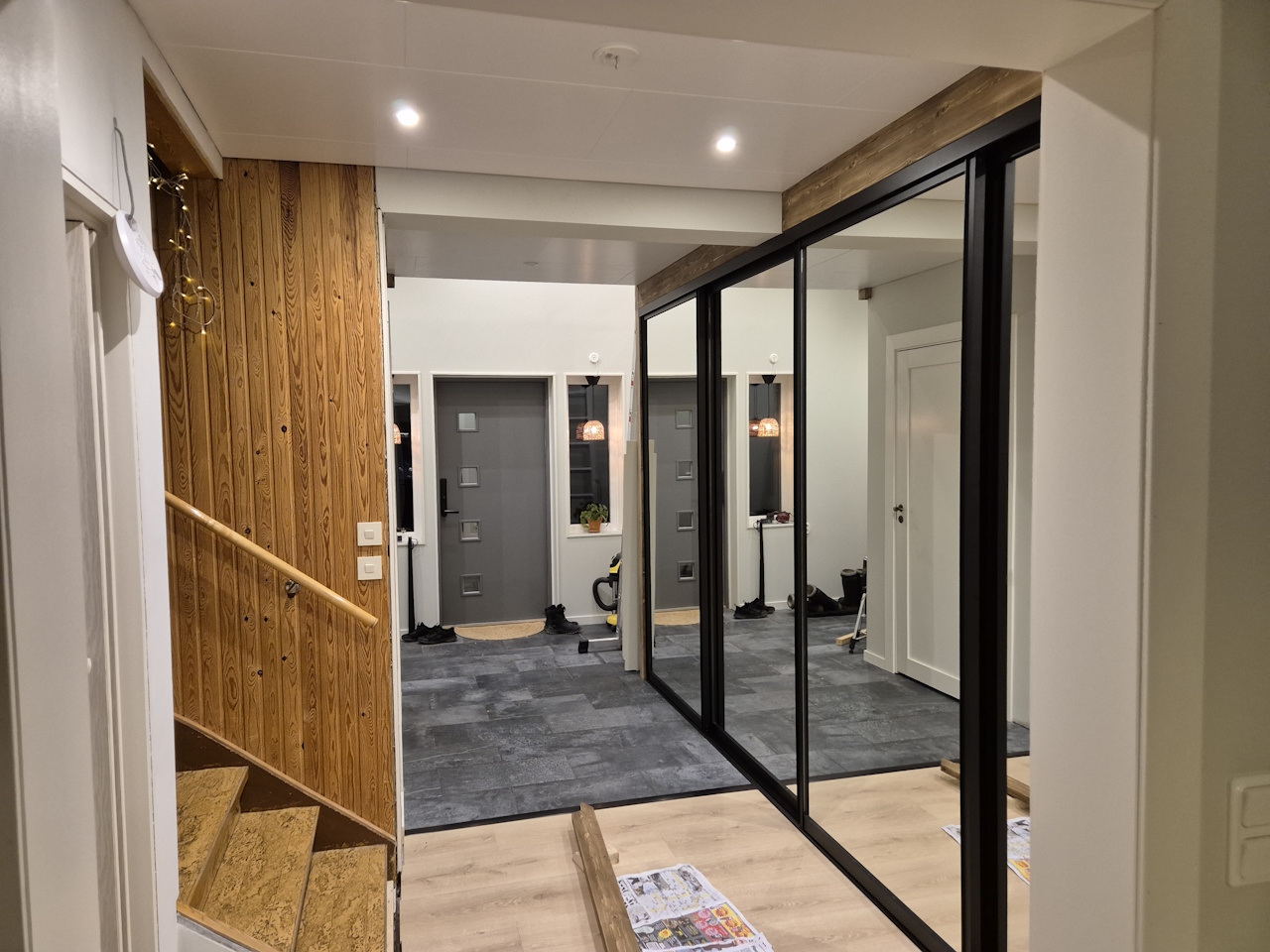
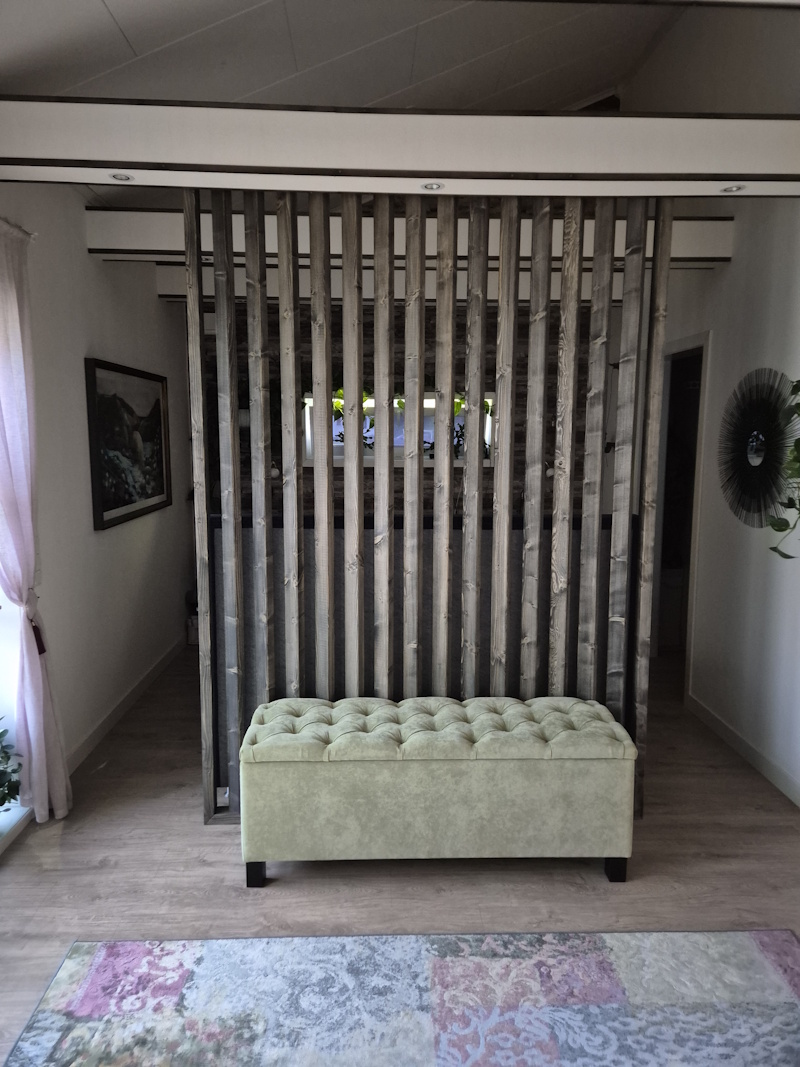
The new entrance to the house incorporates a large wardrobe which we missed in the old one. We’ve got 4m+ to the ceiling so we figured that we needed a sleeping area for guests and built a loft with a proper bed.
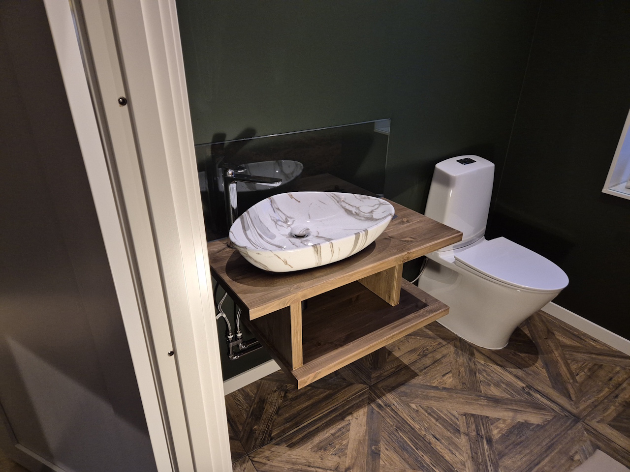
The bathroom by the entrance turned out real nice. All we need now is a mirror to go over the sink and it’s done.
Our bedroom in the extension with a walk-in closet and a huge bathroom with sauna.
This project is the reason for the slow progress on all my other projects. Now that it’s almost done I’ll be posting more frequently about the other fun stuff I’m doing..
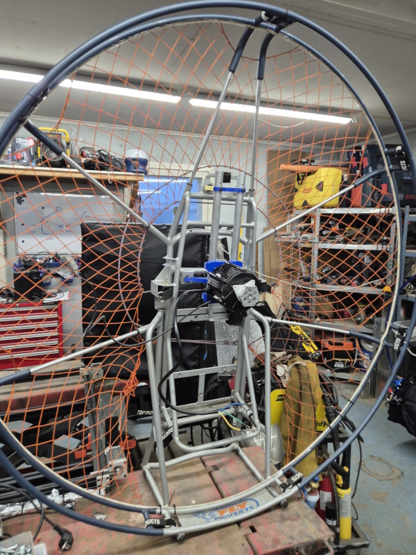
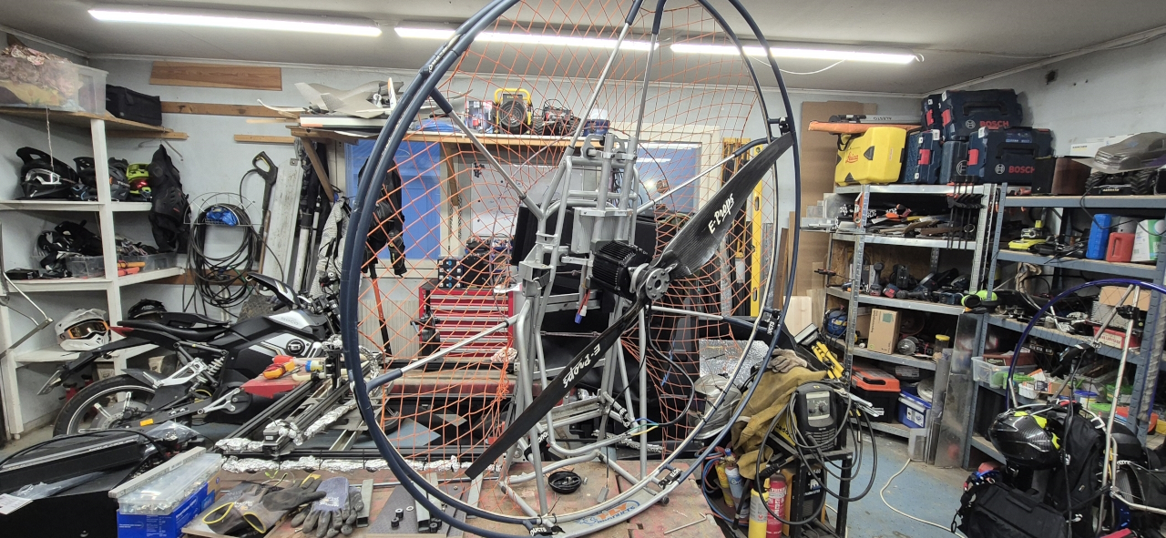
So, since I’ve picked up the hobby of paramotoring of course I’ve got to build one of my own. And since I’m kind of into electric I’ll be designing an all electric paramotor, mostly from stuff I’ve got at home.
The idea is as follows: * A 72v setup using the same batteries and chargers as my bikes initially * Using an LR XL motor, producing approx 17kW peak that I didn’t use for my latest bike * Got a FarDriver 72680 controller as it was dirt cheap and should suffice * 130cm 2-blade propeller that fits my Moster185 so I can use the same on both * Some old scrap frame or whatever I can conjure for a reasonable price until I make one
To keep things simple and lightweight the first version will use the motor extrusion as the load carrying body of the package. There are extra bearings in the yellowish part helping to take the load from the propeller. The reason for the tiny propeller mount is that I’m using 20×60 aluminium stock that I’ve got at home for prototyping. When I see that it works I’ll make a more proper one.
The RPM of the motor should be close to what the propeller needs and we can adjust using field weakening on the controller. If the motor spins to fast I’ll make a belt reduction but first we’ll try out the simplest version.
I’ve paired the motor with the controller and it seems fine. Haven’t dared to hook up the propeller to it before I’ve got a proper mount for it though as that would be a disaster waiting to happen.
To control the motor I’m making a hall sensor throttle that’ll be 3D-printed all the way. I’ve tried to keep it simple and switchable so the same throttle can be used for both right- and left-hand control. I’ll print a prototype and there will probably be a bunch of changes for this before it’s done too..
Just for the fun of it I designed and printed a chasecam too. This one is of similar size and weight as commercial ones and is kept together with locking tabs in the base and TPU clips round the perimeter. It’s very flexible and bounces around when you throw it. I’ve got some paracord on order to try it out..
So, it’s been awhile.. this winter has been hectic with the house renovation and loads of private crap that’s been going on, but it’s all getting to be sorted so maybe this spring will render more time for hobbies.
The house is starting to near completion, to see more about that follow @casa_de_la_runsten on instagram where my wife is documenting that project.
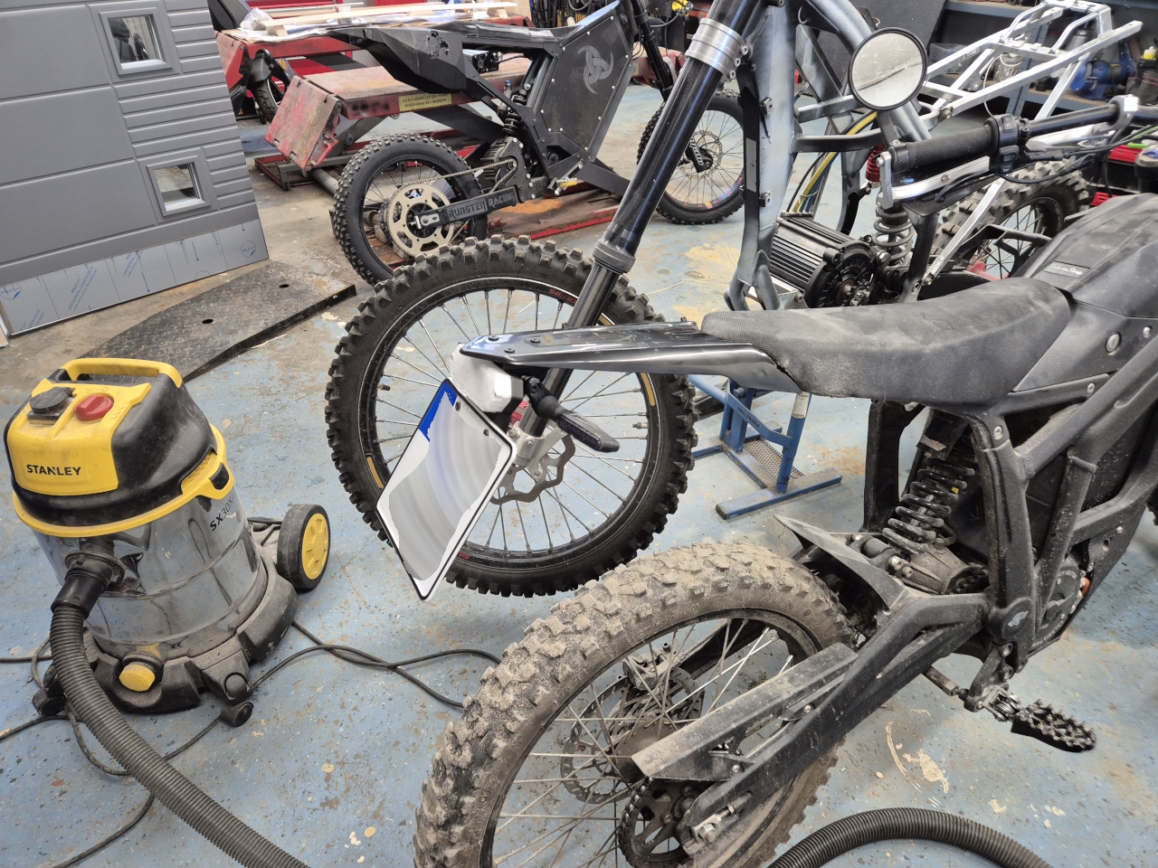
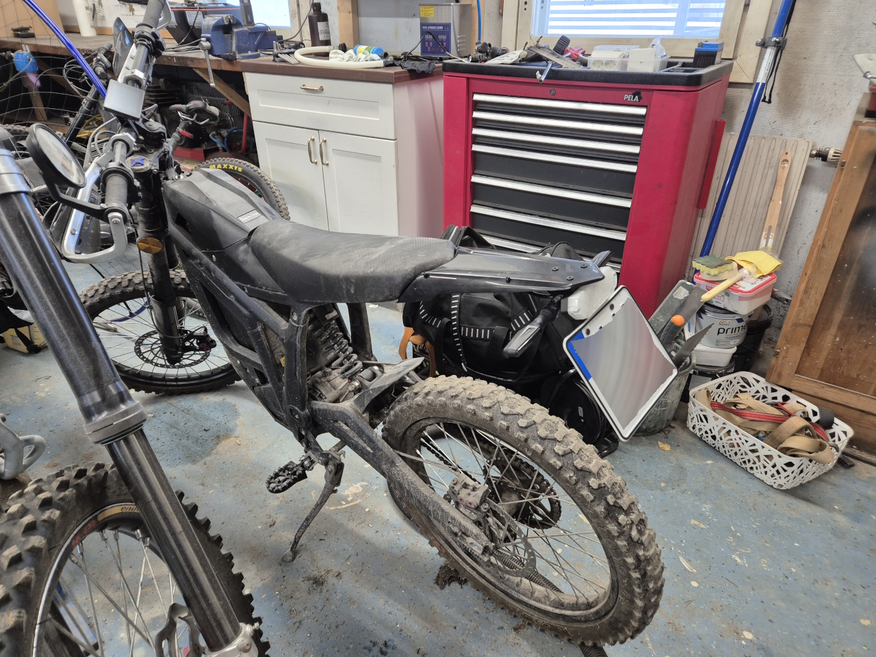
As spring is coming closer it’s time to look over the two wheeled toys again and highest priority among those is the Talaria tail tidy. Since the kid doesn’t want to drive illegaly I needed to fix the tail with all the lights and everything, and it turned out pretty nice.
Don’t mind all the crap in the background. The garage has been storage for loads of my ongoing projects this winter..
Everything works and this should be sorted. One project complete, next up is the electric EC250 which I’ll be building in paralell with the electric ppg..
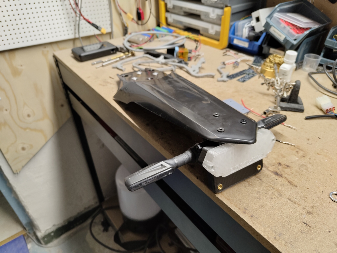
So, we got the kid a Talaria Sting for his 15:th birthday and soon thereafter he flipped it while trying to wheelie. It’s bound to happen and with the original tail ”extension” on the Talaria the entire rear is scrap after such an incident. Tail light, indicators, subframe.. everything is scratched, crushed or bent.
I didn’t get to take any pictures of the bike in that state but after removing the damaged parts and making a quick fix, this is what it looked like.
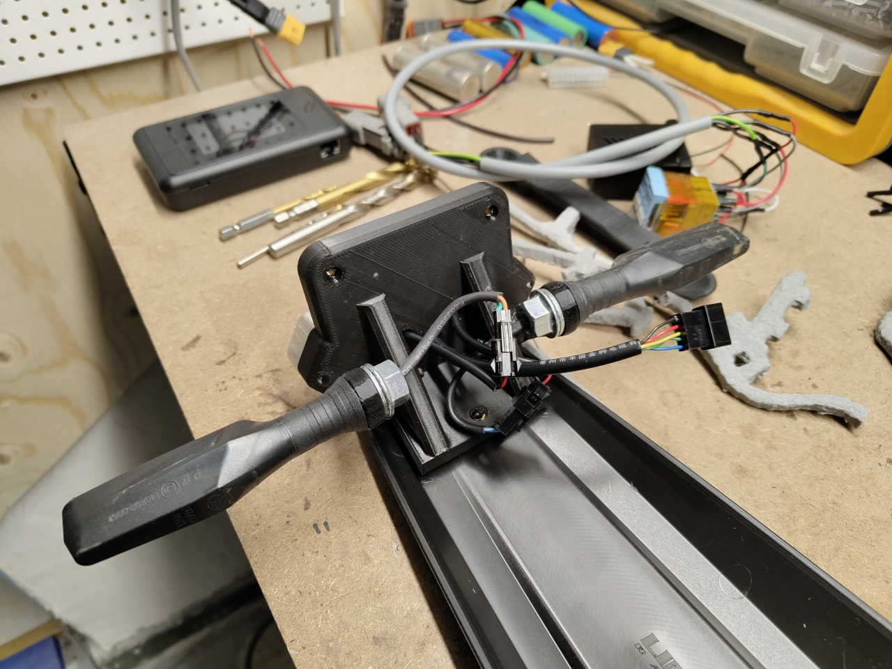
It’s mostly alright and usable but unfortunately the plate hits the rear wheel when compressing the suspension all the way, and that won’t work. So I started working on an upgrade.
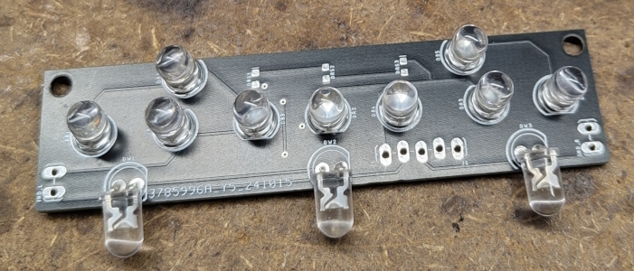
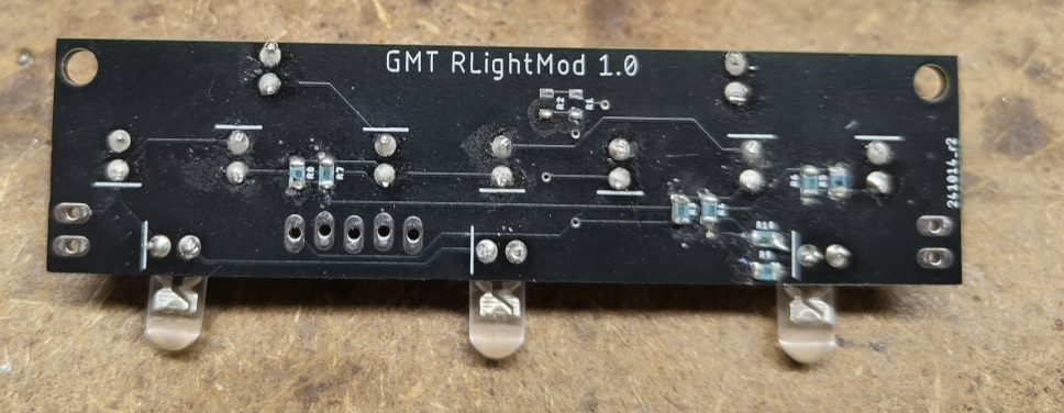
Since the tail light got shattered I started designing a new light that would integrate to the rear part:
I then designed a plate holder with the integrated tail light and holders for the indicators. I made the indicator holders from TPU so they’d rather bend than cause the indicators to break when hitting stuff..
The light casing is made from transparent PLA, even though it looks more white. The light shines through OK but I’ll try tweaking the settings to getting a more transparent print. The lower threads are for bolting the plate to and the light has three integrated white LED:s to illuminate the plate.
Everything is connected using JST-connectors so next crash it’s going to be a quick job replacing whatever’s broken
I’ll post an update when this is mounted on the bike. I might have to adjust the angle of the plate to get it perfect but with this being the longer fender we’ve got a lot more clearance than with the original short one.